

Why a hole must be checked relative to a bend
When a flat sheet becomes an angled part, material near the bend deforms. If a hole is too close to that area, its shape or position may change. A hole that was round and correctly placed in the flat pattern will not necessarily remain suitable for fastening after forming.
The bend distance must therefore be assessed for the finished part and the agreed manufacturing method. A single “centre-to-line” dimension is insufficient if the line's meaning, hole diameter, thickness, radius and bend angle are unclear.
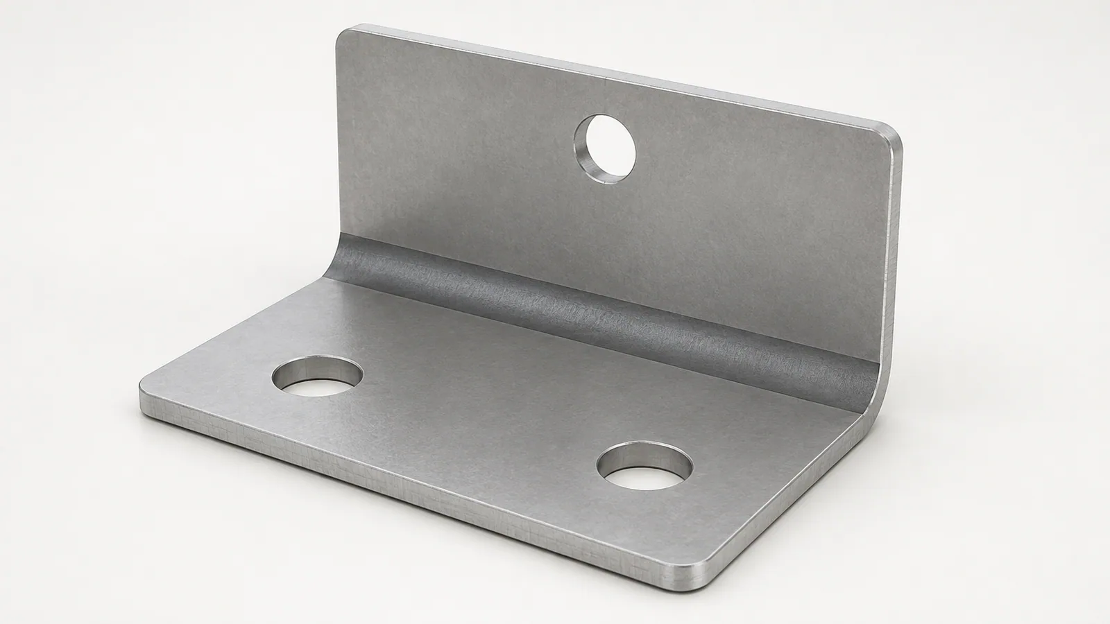
Imagine a bracket with two flanges. A hole in one flange is needed for a bolt but lies close to the transition between the flanges. Your task is not simply to leave an arbitrary allowance on the drawing. It is to ensure that the formed hole retains its function, the fastener fits and the part assembles without forced adjustment.
A bend line is not always a visible edge
In a flat pattern, a bend is often shown by a reference line. In the finished part, a rounded region with a particular radius connects the two flat areas. It cannot be treated as a perfectly sharp fold with no width. Distances to the flat-pattern reference line, the start of the rounded region and the imaginary intersection of the planes are therefore different quantities.
The drawing must show unambiguously where the dimension is measured from. If one person measures from the hole centre to the flat-pattern reference line and another from the hole boundary to a tangent line on the formed part, they will obtain different numbers while possibly believing they are discussing the same thing.
For the customer, supplying the finished-part model and a clear drawing with datums, then agreeing the flat pattern with the manufacturer, is often the most convenient approach. This does not prevent you from preparing the flat file yourself. It simply needs to match the bend geometry actually intended.
| Measurement | Why it is needed | What to clarify |
|---|---|---|
| Hole centre to a defined datum | Fastener position | The datum and the part's state |
| Hole boundary to the bend zone | Risk of hole distortion | Radius, thickness and process |
| Hole to flat-pattern reference line | Preparation of the flat blank | What that line represents |
| Fastener to neighbouring flange | Assembly feasibility | Head, nut and tool dimensions |
What can change about the hole?
During bending, the outer material layers stretch and the inner layers compress. A hole extending into a significantly deforming region may elongate, change outline or develop unwanted distortion around its edge. The outcome depends on hole position, shape and orientation, not just diameter.
A long slot and a round hole may react differently. Consider how the slot lies relative to the bend and which part approaches the deformation zone. Complex geometry can also change local stiffness, so the result should not be judged solely by the shortest distance.
Not every change is equally critical. A small deviation in a decorative opening may be acceptable if agreed. A fit, thread or precision locating feature has different requirements. Explain the hole's function first, then determine the result that must be achieved.
Why there is no universal distance for every sheet
Material, thickness, inside radius, angle, tooling and bending method affect the process. Changing one parameter may change the acceptable hole position. A recommendation in a particular manufacturer's catalogue is useful only when its applicable conditions are understood.
Be especially cautious with advice such as “always leave a few material thicknesses.” It may be an initial guide for a particular process, but it does not replace drawing verification. Different recommendations may also measure from different references: the centre, hole boundary or tangent to the radius.
Do not choose a punch and die independently solely to accommodate the hole. The manufacturer assesses available tooling together with the entire part shape. A smaller radius or different tool is not automatically an improvement: forming suitability and product requirements must still be preserved.
Example: a bolt hole in an angle bracket
Suppose a bolt must pass through a hole in a bracket's vertical flange. A horizontal flange is nearby, and the hole lies close to the inside corner. Even if the hole itself remains usable after bending, the bolt head or washer may interfere with the radius or neighbouring flange.
First check the hole position in the finished model. Then include the fastener's real dimensions and tool access. Do not assess this only along the bolt axis: its head, washer, nut and insertion direction matter for assembly. Restricted access may require a different assembly sequence or a design change.
The manufacturer then assesses how bending affects the hole. If relocation is necessary, coordinate it with the mating part to which the bracket attaches. Moving the hole to a production-friendly position is insufficient if the assembly's holes no longer align.
For a repeat order, check not only one bolt but repeatable assembly within the agreed tolerances. A part assembled only after filing or forceful clamping does not prove correct geometry. The criterion should reflect the normal installation method.
What can change if the hole is poorly positioned?
The simplest option is to move the hole away from the bend zone where the design permits. Sometimes the flange can grow, the fastening arrangement can change or the cutout shape can be reconsidered. Every change must preserve part function, dimensional constraints and assembly compatibility.
Another option is to make the hole or finish-machine it after bending. This may help achieve certain requirements but adds operations, setups and tool-access questions. Do not promise that this route is always cheaper or technically possible. The manufacturer must assess it for the actual shape.
A special relief cutout that changes material behaviour near the bend is sometimes considered. This is part of the design, not a cosmetic edit. It may affect strength, sealing and appearance, so it requires separate agreement.
Do not intentionally draw a distorted hole in the hope that bending will “make it right” without a verified process. Such compensation can be a specialised manufacturing solution, but an arbitrary shape chosen by eye does not produce predictable results.
What the drawing should contain
Show the finished shape, material, thickness, bend angle and inside radius, plus hole dimensions and positions relative to clear datums. State which dimensions are inspected after forming. If you supply a flat pattern, identify the bend lines and which lines are not intended for cutting.
Separate finished-part requirements from supporting manufacturing information. For example, hole position after bending may be functionally critical, while a particular flat-blank dimension depends on the agreed process. Without that distinction, two formally correct but incompatible versions may result.
Do not specify an angle only as an ambiguous number without a view. Different systems may name rotation angles and internal angles between flanges differently. A sketch of the finished part and a clear dimension help prevent mistakes before manufacture.
When thickness changes, check the model and flat pattern again. The old bend-line position may no longer match the new version. Likewise, material or radius changes should not exist only in an accompanying message while the file remains from the previous revision.
If holes on both flanges must work together, check their relative positions after bending. Individually correct distances in a flat blank do not guarantee coaxiality or the required spatial distance. The angle and transition geometry affect the outcome, so state the requirement for the finished assembly.
At the same time, do not apply excessively tight tolerances to all holes equally. A free cable passage can have different requirements from a precision locating feature. Explaining the function helps the manufacturer and designer distinguish genuinely critical dimensions from those adequately served by the usual agreed accuracy.
Remember bend direction too. A seemingly symmetrical flat pattern can produce different flange orientations after forming. A hole can retain the same flat coordinate yet end up on the wrong side of the assembly. A clear view of the finished shape and direction indications help catch this before production, without complex calculations or remanufacture.
How to check a trial part
Before trial manufacture, agree exactly what will be checked: hole shape, position relative to datums, angle, radius or fastener installation. If a precise fit is needed, a photograph is insufficient. Measurements or a functional check under agreed conditions are required.
Check the part in the state in which it will be supplied. If hole machining or coating follows bending, the final result may differ from the intermediate state. Record this sequence in a report or short working note.
One successful sample helps confirm a solution but does not remove the need for batch control. For a critical joint, permitted variations and their inspection method must be understood. A trial's purpose is not merely to show that the metal bent, but to confirm the finished part's suitability.
How to phrase the request to the manufacturer
Supply the model and drawing, and explicitly identify the hole close to the bend. Explain its function and fixed requirements. For example: “This hole attaches to an existing frame; its position after bending is critical. Please assess hole deformation and bolt access. Geometry changes require approval.”
Include quantity, material, thickness and subsequent processing information. If making the hole after bending is acceptable, say that the option can be assessed. This tells the manufacturer which solutions are worth considering and which conflict with your task.
After agreement, retain one current revision. A corrected dimension in a message must not contradict an old DXF or model in the attachment. A clear document set matters more here than a long list of technical terms.
Assess holes and bends in a part drawingWhat counts as a correct result?
A correct result is a hole with the required shape, position and function after bending. The distance in the flat pattern helps achieve that, but is not the final objective itself.
Check the reference used for the dimension, the bend-zone location, fastener operation and subsequent processes. Where changes are needed, agree them as part of the design or manufacturing method, not as a random file edit.
This gives a clear sequence: define finished-part requirements, agree geometry and process, then verify the result. It is more reliable than searching for one universal distance supposedly suitable for every hole and every bend.