

Why a small cutout is added at a corner
A bend relief gives neighbouring sheet areas room to form. It helps reduce the risk of tearing, bulging or unwanted distortion where a bend ends near an edge or meets another flange. It is not a randomly removed piece of metal, but a considered design feature.
Imagine a box made from a flat blank. Its walls must fold upwards, but material from two adjacent walls cannot indefinitely occupy the same space at the corner. Without appropriate separation, forming can produce an unwanted result. A relief helps organise this transition.
A larger relief does not automatically mean a better part, however. It changes the edge, stiffness, appearance and the ability to close the joint. Its shape and dimensions should therefore be chosen alongside finished-product requirements, not merely to “make bending easier.”
What problem should the relief solve?
Start by asking what is obstructing forming. In one case, only part of a long edge bends while the neighbouring area must remain flat. In another, two flanges meet at a box corner. In a third, a nearby cutout or feature must retain its shape.
The first case requires separation of the area moving during bending from the area that should not move with it. A box corner requires consideration of the walls' relative positions after forming. These tasks are related but not identical, so copying one relief into every location without checking is unwise.
If the problem is excessive overall material deformation or unsuitable tooling, the relief alone does not guarantee a remedy. Its role is local. Material, radius, thickness and forming method still need to be agreed.
| Situation | Purpose of the relief | What else to check |
|---|---|---|
| Only part of an edge bends | Separate moving and flat areas | Where the bend ends |
| Two walls meet at a corner | Provide room for forming | The finished wall joint |
| Important geometry is nearby | Reduce unwanted forming effects | Its dimensions after bending |
| The corner must be closed | Coordinate forming with later closure | Welding, sealing or assembly |
What shapes are possible?
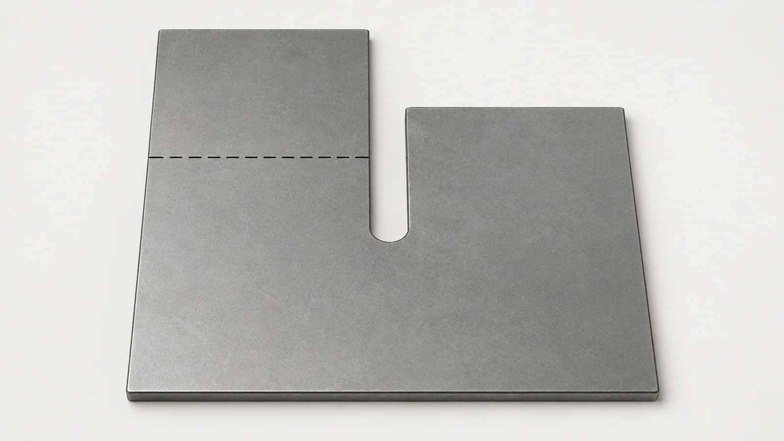
A relief can be rectangular, rounded or another agreed shape. Rather than calling one version best for every case, understand how it works in the actual part. The choice depends on location, material, manufacturing method and corner requirements.
A rounded end may be appropriate where an abrupt transition at the end of a notch should be avoided. However, it also removes material and must fit between neighbouring features. A rectangular relief may suit a particular joint, but its corners and dimensions also need assessment.
Do not leave the shape to a verbal instruction to “cut out something small.” If the relief affects function or appearance, show it in the model and drawing. Everyone can then discuss the same geometry rather than different assumptions about what the manufacturing specialist should do.
Width, depth and location: what must be specified?
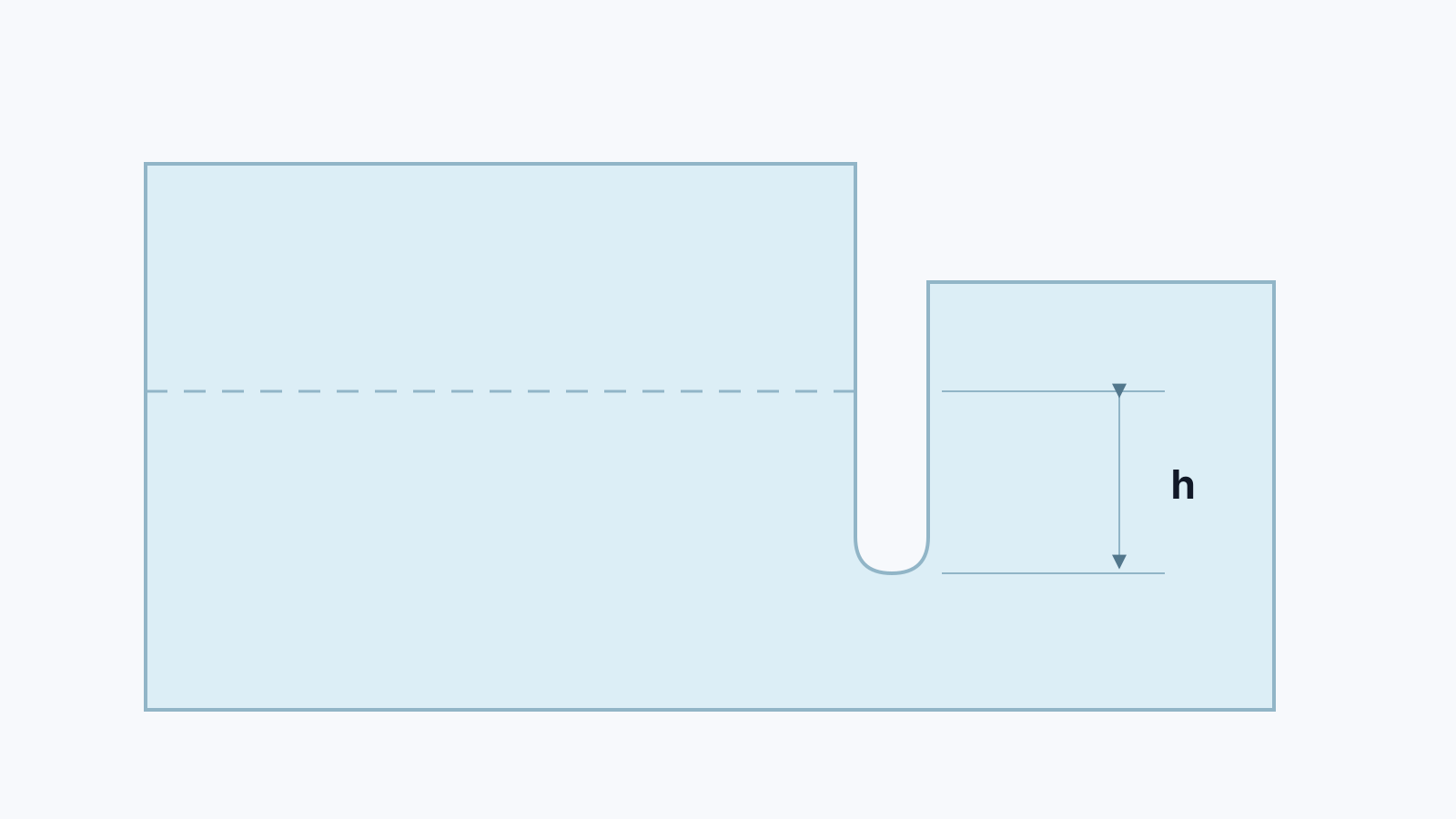
Width determines how much material is removed across the relief. Depth describes how far it extends into the blank. These words make sense only with defined references, however. Depth from the sheet edge and distance from a flat-pattern bend line are not the same measurement.
The relief must cover the area needed for forming without removing useful material unnecessarily. Its particular limits depend on radius, thickness, angle and process. Apply a manufacturer's recommendations only to the conditions and measurement references for which they were provided.
Show the contour, relevant dimensions, radii and position relative to the bend. If a finished-part model is available, inspect the relief in both flat and formed states. It may look sufficient in the flat pattern yet leave an unwanted gap or interfere with a neighbouring wall after forming.
Do not specify width only through the thickness of a displayed line. Cutting needs actual boundary geometry. Similarly, do not send an open short stroke and expect the manufacturer to decide the slot width: it must match the agreed process and finished-relief requirements.
What changes in the finished product?
Removing material changes local stiffness and may affect load transfer. If the corner belongs to a load-bearing feature, verify the solution as a design, not merely a manufacturing convenience. A neat bend does not prove adequate strength.
For a housing, dust or moisture protection and cleanability may matter. A relief creates an opening or gap that must be closed appropriately where required. Subsequent painting alone does not make that corner leak-tight.
Discuss appearance before manufacture too. Even a technically valid relief can look unsuitable on a visible panel. It may need relocation to a less conspicuous area or a different joint design. That is a design decision, not justification for an undisclosed file change in production.
Example: a small box with two adjacent walls
Suppose a box is made from one sheet. Two walls should form a tidy corner after bending. First determine whether they merely meet, connect with fasteners or will be welded. This determines the required joint after forming.
Next check the flat pattern, radii and bend sequence. The corner relief must allow the walls to form without unwanted interaction, but should not grow until an unapproved large opening has to be closed later. Both states must correspond: the flat blank and the finished box.
If welding is planned, agree the joint shape with the person responsible for that operation. Welding can introduce its own distortion and requirements for access, edge preparation and subsequent dressing. Do not assume every bending defect can simply be “welded up later” without consequences.
For a trial box, check the corner, relative wall positions, edge condition and actual gap. If a lid is required, try it on as well. This assesses product function rather than only the attractive appearance of one bend.
Mistakes that are easy to make during preparation
The first is adding a relief after all dimensions are agreed without updating the finished-part model. The customer then expects a continuous corner but receives an opening. Production may follow its file exactly while the document set already contains a contradiction.
The second is enlarging the relief to solve any forming problem. If the cause is material, tooling or an incorrect radius, removing more metal will not necessarily help. Understand the defect first, then choose the relevant change.
The third is copying geometry from another thickness without checking. Changing the sheet can change the radius, flat pattern and room needed for forming. An old relief does not become correct simply because it worked in a superficially similar part.
The fourth is forgetting burrs and sharp edges. Even a correctly cut corner may need deburring according to product requirements. This is particularly important wherever hands, cables or seals can reach. Agree the requirement rather than assuming it will be fulfilled automatically.
Check separately whether the relief has moved too close to a hole, slot or fastener. A thin web may now remain between two features where none existed in the original model. Looking only at the bend makes this easy to miss. Assess the entire local area, not the relief in isolation.
For symmetrical parts, do not rely solely on copying. Left and right corners may have different neighbouring features or forming sequences. Mirrored geometry can be appropriate, but its function must be checked in both locations. This matters particularly when one corner stays open and the other is closed by another part.
If the specialist proposes another shape, ask to see it in the file or a clear sketch. A verbal “we will make it a little deeper” does not define the starting reference or the amount of change. After approval, update the document used for cutting and preserve consistency with the finished-product model. This keeps the decision from being lost between design, cutting and bending.
Checking the solution before series production
For a simple repeat part, a verified model and agreed process may suffice. For a new complex corner, consider trial manufacture. The sample should represent actual conditions: material, thickness, geometry and operation sequence.
Define criteria before checking. For example, is visible bulging acceptable, what joint gap is required, and which dimensions and edge conditions matter? A leak-tightness requirement needs a separate appropriate test of the finished joint. No visible opening is not, by itself, proof of leak-tightness.
Record the result and revision. If the relief changes after the trial, reassess its effect on neighbouring features. There is no need to redesign everything, but check the requirements affected by the change.
Inspect the product after subsequent processing too. Dressing, welding and coating can change joint appearance or reveal locations requiring tool access. Assessing only the freshly bent blank can leave problems unnoticed until the batch is finished.
What to include in a manufacturing request
Provide the model, drawing, material, thickness and quantity. Explain the corner's function: visible, load-bearing, closed, intended for welding or assembly. State which relief changes may be proposed and which require separate approval.
For example: “Box with two adjacent bends. The formed corner will be welded and dressed; the outer surface is visible. Please assess the flat-pattern relief and joint access. Shape and dimensional changes require approval.” This helps the manufacturer consider the complete route, not just bending.
After agreement, retain one current file set. If the drawing and model describe different corners, do not ask the specialist to decide which matters more. Resolve the contradiction before releasing the part for work.
Discuss bends and reliefs in a part designWhat makes a good bend relief?
A good relief is sufficient for the agreed forming process without removing material unnecessarily. It has a clear function and defined geometry and creates no unapproved problems with the joint, strength or appearance.
Start with the finished product: what should form at the corner, how it works and which operations follow. Then agree flat geometry, radii and process with the manufacturer. Where necessary, inspect a trial part against specific criteria.
This makes a small relief a controlled design feature. It does not guarantee flawless forming under every condition, but helps produce a predictable result when correctly connected to material, geometry and product requirements.