

How close can a hole be to an edge?
A hole can be placed close to an edge only when the remaining strip of material is sufficient for manufacturing and for the part's intended use. The answer depends not on one number but on geometry, material, thickness and the hole's purpose. A laser's ability to cut the outline does not prove that the edge will withstand fastening, further processing or loads.
Imagine a small mounting plate. Its hole has been moved closer to the outer boundary to match an existing bracket. The change looks minor on the drawing, but a narrow area remains between the hole and the edge and may become a weak point. It must retain its shape during cutting and perform its function after assembly.
The right approach is therefore to check manufacturing feasibility and design suitability separately. The manufacturer assesses the process, while the person responsible for the part defines strength, assembly and use requirements. These checks complement rather than replace each other.
Measuring from the centre or from the hole boundary
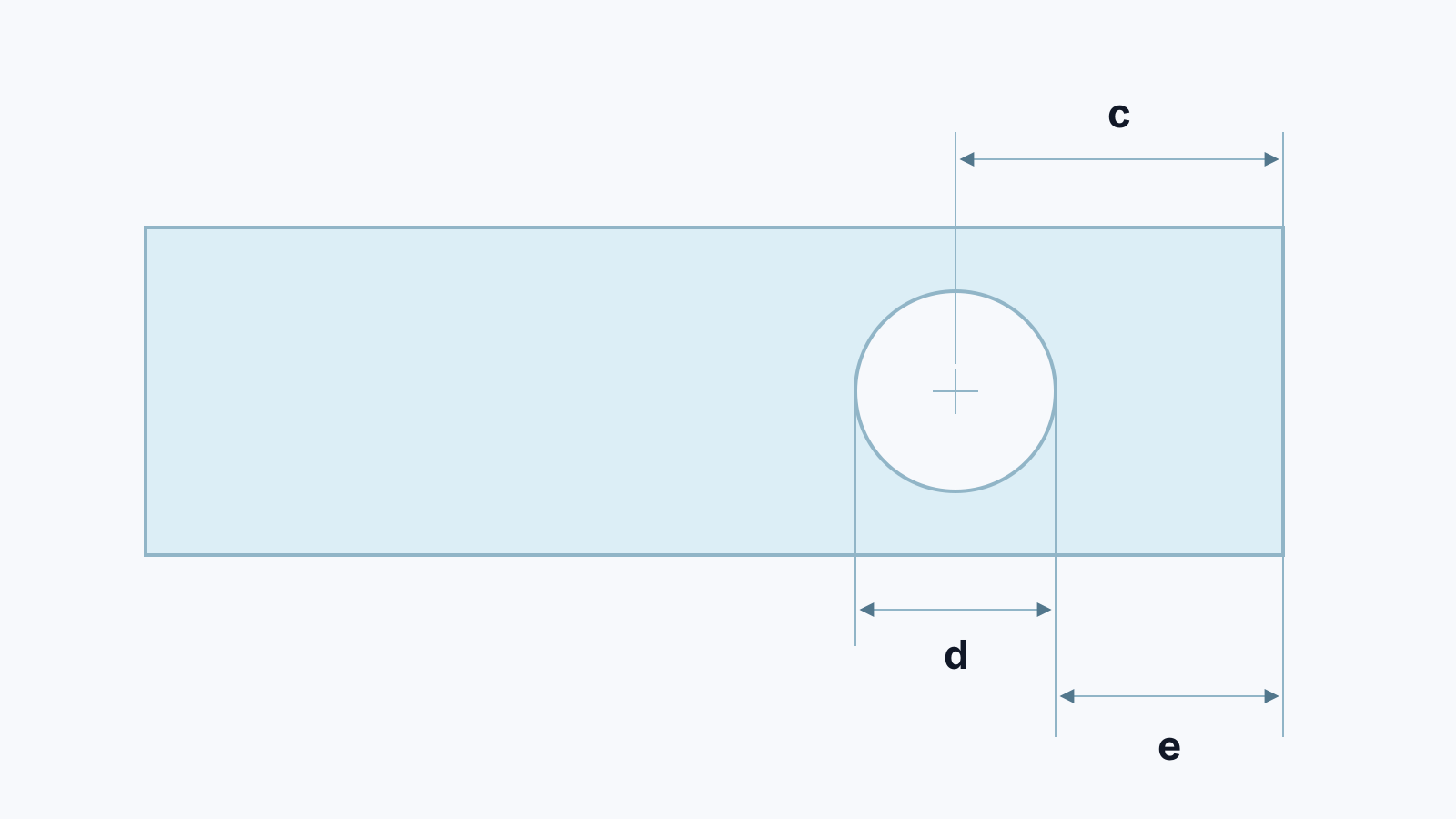
Drawings often specify the distance from a hole's centre to an edge. Assessing the narrow area requires another dimension: the shortest distance from the hole boundary to the part's outer boundary. Confusing these two measurements can substantially overestimate the material remaining.
For a round hole beside a straight edge, subtract the radius from the centre-to-edge distance. For example, if the centre is 8 mm from the straight edge and the hole diameter is 6 mm, the nominal material remaining between their boundaries is 5 mm. This is a geometric example only, not a recommended minimum.
For a slot, oval hole, shaped cutout or curved outer edge, assess the shortest distance between the relevant boundaries. It may not be where a convenient dimension happens to be placed on the drawing. Examine the actual shape, especially near corners and rounded sections.
| Dimension | What it describes | Why it matters |
|---|---|---|
| Centre to edge | Hole centre position | Fastener placement and assembly |
| Hole boundary to edge | Remaining material | Assessing the narrow area |
| Diameter or slot width | Hole size | Fit and calculating the remaining width |
| Dimensional tolerances | Permitted variation | Checking the smallest allowable remaining section |
Why hole shape changes the assessment
A circular hole and a long slot near an edge can have the same minimum edge distance yet leave areas that behave differently. Beside a circular hole, the narrowing is local. A long parallel slot creates an extended narrow strip that may be more sensitive to bending and handling.
Position near a corner matters too. If a hole is close to two outer sides simultaneously, the surrounding material differs from that around a hole midway along a broad edge. Assess both directions, not just the dimension that passed a formal check.
Do not judge by diameter alone. For a fastener hole, the load direction and neighbouring features matter. For a decorative cutout, appearance and resistance to accidental pressure may be more important. One geometric distance cannot describe all these different tasks.
What happens to the edge during cutting?
The laser heats material in the cutting zone. When a hole lies close to the outer contour, the narrow area sits beside several processed boundaries. Its behaviour depends on heat input and removal, geometry, and how much support remains from the rest of the sheet.
Cutting contours can change stiffness and redistribute residual stresses. A long strip near an edge sometimes distorts even though the sheet appeared flat beforehand. However, it is not possible to claim in advance that every nearby hole will cause deformation. The outcome needs assessment in the actual process.
Operation order, nesting, supports and part retention belong to production preparation. Customers do not need to prescribe them by guesswork. It is more useful to identify the critical edge and explain whether it is an assembly datum, a visible surface or simply a free boundary with no precise mating requirement.
Cutting a hole and making a reliable fastening are different tasks
If the hole is for a bolt, the narrow remaining material must carry forces according to the joint's design. Depending on the conditions, bearing deformation, tear-out towards the edge or other failure modes may be possible. These should be assessed using loads, material, thickness and how the joint operates.
A manufacturer's statement that “we can cut that hole” is therefore not a strength calculation. Loaded or critical parts need a designer's verification. A universal suggestion to “add a washer and it will be fine” is also unacceptable: a washer does not automatically correct insufficient edge distance.
Check space for the bolt head, nut, washer and tool separately. A hole can be geometrically well positioned while the fastener does not fit or cannot be tightened. This is particularly easy to overlook near bends, flanges and neighbouring housing components.
Which subsequent operations must be considered?
After cutting, a hole may be countersunk, machined, used for special hardware or positioned near a bend zone. Each operation has its own requirements. A minimum sufficient merely to cut a simple hole does not necessarily suit subsequent processing.
For example, countersinking increases the hole diameter near the surface. Looking only at the original through-hole diameter may conceal how close the machined area comes to the edge. Show the final shape in the drawing rather than leaving it to a verbal explanation.
Deburring and transport also matter. A thin edge may be damaged by clamping or snagged while the part is moved. If appearance is critical, agree acceptable marks and handling methods. Finished-product requirements should cover the whole route, not only the moment the part leaves the machine.
Example: a mounting slot beside a long edge
Suppose a plate contains an elongated slot for positional adjustment. It runs parallel to a long outer edge, leaving a narrow strip. Adjustment is necessary, so simply replacing the slot with a round hole is not an option. A solution must preserve the function.
First establish the required adjustment travel, fastener position and available space. Then assess whether the outer dimensions can increase, the slot can move or shorten, or the joint arrangement can change. These are options for the designer, not automatic corrections the manufacturer should make without permission.
If the geometry cannot change, the manufacturer assesses feasibility in the agreed process. A critical case may require a trial part. Check not only that the slot exists but also the narrow edge's shape, dimensions, fastener fit and adjustment function. That is how a trial answers the customer's real question.
Do not accept the sample solely from a photograph. An image helps reveal an obvious defect but does not confirm dimensions or joint performance. If the part must assemble with other components, check it under appropriate conditions or use an agreed measurement method.
Why dimensional variation matters
The nominal distance between a hole and an edge is the value intended in the drawing. Actual dimensions and positions have permitted variations. If the narrow area is critical, assess the smallest remaining section possible within the agreed requirements.
Do not simply add arbitrary figures from different catalogues. What matters is how the particular drawing defines dimensions, datums and tolerances. Where necessary, the designer determines the dimensional stack-up, and the manufacturer confirms whether the process can meet the requirements.
Nor should you add an arbitrary kerf allowance to the drawing if the manufacturer expects finished-part geometry. Kerf compensation belongs to toolpath preparation. Double compensation can change both the hole and the outer edge, and therefore the strip between them.
Agree the measurement method for acceptance too. A small burr or surface irregularity may interfere with assessing the actual geometry, while pressing on a thin strip during measurement may temporarily conceal distortion. Decide beforehand whether the part is checked after cutting, after deburring or after all operations. This allows like-for-like comparison instead of disagreement caused by different inspection conditions.
If the edge is an installation datum, consider its shape together with the hole position. A correct diameter does not help if the datum itself has shifted or distorted enough to make the part sit differently. An unloaded decorative panel may have simpler criteria, but they should still be stated—for example, preservation of the pattern and no noticeable edge damage under agreed viewing conditions.
Not every scratch or processing mark means a loss of strength, and not every geometric deviation is visible. Appearance, dimensions and function should therefore be assessed separately. This does not complicate ordering: it avoids paying for unnecessary requirements while ensuring that features genuinely affecting performance are not missed.
For repeat orders, specify the same agreed revision, material and processing route. A thickness change or added countersink changes the conditions even if the hole centre remains in the same position. Previous successful manufacture is then useful experience, not automatic confirmation of the new version.
What to ask the manufacturer
Provide material, thickness, quantity, the drawing and the hole's purpose. Mark the narrow area and state what the edge must achieve: retain flatness, meet a dimension, survive further processing or remain a tidy visible surface. A more precise description of the required result produces a more specific answer.
For example: “Mounting plate with an adjustment slot near the edge. Slot position and overall dimensions are tied to assembly; changes require approval. Deburring follows cutting. Please assess the stability of the narrow area and whether a trial sample is required.” This is much more useful than asking “What is the minimum edge distance you cut?”
If the manufacturer proposes moving the hole, do not approve it merely as a way to simplify production. Check compatibility with the mating part and the joint's function. Once approved, retain one current drawing revision so the old file cannot enter production.
Assess a part with a hole close to the edgeMaking a justified decision
Start with a correctly measured boundary-to-boundary distance, not just a centre distance. Then consider the narrow area's length, hole shape, material, thickness and later operations. Separately check the function of the fastening or other feature for which the hole exists.
A good solution does not necessarily place every hole as far from an edge as possible. Compactness, adjustment or compatibility with an existing assembly may be required. The task is to find geometry that is both manufacturable and suitable for the design, not apply an arbitrary rule to every part.
If doubts remain, submit the actual file for assessment and agree how to verify the result. The edge-distance question then stops being a search for one magic number and becomes a clear decision for your part.