

When rolling direction needs to be specified
Specify rolling direction when blank orientation affects agreed properties or manufacturing requirements. This is particularly important for certain materials and bends where the sheet producer gives different recommendations according to direction. But do not add the requirement automatically to every drawing: it should serve a real purpose.
The notation itself is straightforward: a clear labelled arrow referenced to part geometry. The more demanding task is maintaining that orientation during nesting, cutting and subsequent processing. An arrow on a drawing is useless if nobody has confirmed the source sheet's direction.
Imagine a batch of identical brackets. They can be arranged on a sheet in different orientations to save material. If orientation matters for bending, those rotations must respect the requirement. Otherwise, blanks that look identical can encounter different forming conditions.
Rolling direction in plain language
During rolling, metal passes between rolls that change its thickness and shape. Its direction of travel through that process is called the rolling direction. Processing affects the material's structure, and some properties may differ along and across that direction.
This directional dependence is called anisotropy. The key point is that sheet does not always behave identically at every blank orientation. The size of the difference depends on the particular material, its condition and the property being assessed.
Do not imagine metal as wood with obvious fibres. Visible surface streaks do not always reliably identify rolling direction. A production requirement needs material information and a retained link to the sheet, not a visual guess.
How this relates to bending
For some sheet materials, the permissible radius or susceptibility to cracking during bending may depend on the bend line's orientation relative to rolling. For certain high-strength steels, for example, the producer recommends placing the bend line transverse to the rolling direction where possible. This is a material-dependent recommendation, not a rule for all metal.
Be clear about what is transverse. The relationship concerns the bend line and rolling direction, not the punch's direction of movement. If the wording is unclear, show both lines in a sketch rather than leaving an unexplained instruction to “bend across.”
Orientation does not replace checks of material, thickness, radius, edge condition and tooling. Even a favourable direction cannot guarantee freedom from defects in an unsuitable process. Follow recommendations for the specific material and agree forming with the manufacturer.
How to show the requirement on a drawing
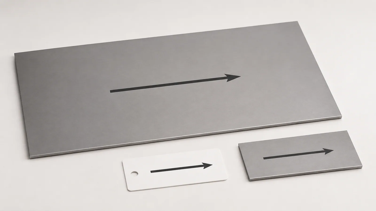
On the flat-part view, show an arrow labelled “Rolling direction.” Reference it to a clear side or axis—for example, “Rolling direction parallel to long side A.” Side A must be unambiguously identifiable, and the arrow must not look like an indication of movement, bending or grinding.
If the requirement concerns a particular bend, show that bend line and explain the required relationship. Do not rely only on page orientation: a drawing can rotate during printing or viewing without changing the geometric requirement.
Model and flat-pattern indications must agree. For a complex part, a separate flat-state view is useful because orientation can readily be checked before forming. After bending, an arrow on an arbitrary face may no longer explain how the blank lay in the original sheet.
| What needs explaining | Clear indication | What to avoid |
|---|---|---|
| Direction in the blank's plane | Labelled arrow | An unlabelled arrow |
| Reference to the part | Parallel to a defined side or axis | “Along the page” without a datum |
| Bend requirement | Both rolling direction and bend line shown | Ambiguous “bend across” |
| Visible surface texture | Separate finish requirement | Confusing it with rolling direction |
Rolling direction versus surface texture
Decorative sheet may have a directional brushed or otherwise finished texture. Panel appearance can depend on consistently orienting that pattern. But the texture direction after finishing should not automatically be treated as the metal's rolling direction.
If both requirements matter, specify them separately. One may define material orientation for forming, the other the direction of visible brushing on the front surface. The manufacturer must check whether the selected sheet can satisfy both simultaneously.
Do not rely on protective film without clarifying its markings. Arrows or text may concern the finish or supply arrangement. Confirm their meaning, especially when orientation affects not only appearance but bending suitability.
Keeping the direction from sheet to individual part
First establish the source sheet's direction using supplier information, identification and relevant production records. A certificate alone does not necessarily show how a particular cut sheet lies on the table, so an actual link between document and material is required.
Next, account for orientation in the nesting layout. Once a blank is cut and separated, its link to the sheet must not disappear before the next operation. Agreed marking, a cutting layout or another clear tracking method can provide this. The method should suit production conditions and surface requirements.
Do not independently scratch deep orientation marks near a future bend. Surface damage may be undesirable. Agree the marking method, particularly for critical, decorative or surface-defect-sensitive parts.
The same applies to sheet remnants. If an offcut has lost its confirmed orientation, do not assign one by assumption simply because its longer side looks like the rolling direction. Recover reliable information first or agree another solution.
Why the requirement can affect price
With unrestricted orientation, nesting software has more options for rotating parts. A directional restriction may reduce layout freedom and change sheet utilisation. It can therefore affect material consumption and cost.
This does not mean removing the requirement to save money. If direction matters to the design or process, preserve it. Equally, adding a restriction without a reason is undesirable: the customer may pay for a condition that does not improve the result.
Clarify permitted rotations and mirrored placement separately. A rolling-axis requirement and a visible-face requirement may restrict them differently. There is no need to invent universal permissions: agree them for the actual product and reflect them in cutting preparation.
Example: a bracket with two perpendicular bends
Suppose a part has two bend lines at right angles to each other. One rolling direction cannot be perpendicular to both simultaneously. A short instruction that “all bends must be transverse to rolling” may therefore be impossible for this geometry.
Assess each bend according to material, radius and requirements. The chosen material may permit both orientations under the required conditions. Alternatively, a radius change, another material or design revision may be needed. Decide using actual data, not by arbitrarily rotating the flat pattern.
Give the manufacturer the model and identify the critical bend. Any trial manufacture should use the agreed orientation. Otherwise, a successful sample will not explain what happens to parts cut differently during series production.
This example shows why the requirement exists: not to add an arrow, but to support an agreed solution. When shape, material and process are compatible, the indication helps repeat the result. When they conflict, an arrow does not resolve the contradiction.
What to supply with the drawing
Specify material, grade and condition, thickness, quantity and required orientation relative to geometry. Explain the reason: forming, properties or, separately, appearance. If the requirement comes from an agreed specification, the manufacturer needs to understand which material it applies to.
For example: “Bracket from the specified sheet grade and thickness. Rolling direction parallel to side A as drawn. Preserve orientation during nesting and transfer to bending. If the supplier cannot confirm sheet direction, approval is required before manufacture.” This is a specific, verifiable condition.
Do not demand a direction indication retrospectively when parts have already been cut without retaining traceability. If the information is unavailable, record that honestly and determine the next steps. An invented arrow does not restore material provenance.
Agree material and rolling direction for manufactureDo not automatically transfer the drawing's arrow into the cutting layer. If it enters manufacturing geometry as an ordinary contour, it can be mistaken for a part feature. Separate explanatory indications from what should be cut or marked on the metal. If the blank needs a physical mark, agree its location and method separately.
Also clarify whether the requirement concerns only an axis direction or whether a particular side and surface orientation matter. Rotating a blank in its plane and turning it over are different actions. On one-side-finished sheet, they can have different consequences even if the relationship between the rolling axis and bend line stays unchanged.
At acceptance, a simple visual inspection cannot always reliably establish the finished part's orientation. Important requirements therefore need material preparation and transfer records, not only a check after every operation is complete. An agreed confirmation method is cheaper and clearer than trying to prove blank provenance after offcuts and identification have been lost.
For a small order, this does not necessarily mean elaborate paperwork. An unambiguous cutting layout, retained sheet identification and an agreed marking on the blank batch may suffice. What matters is that the method genuinely traces the requirement without conflicting with surface requirements. The necessary level of evidence for critical products is determined separately.
Checking that the requirement works
The check consists of three simple questions: is orientation justified for this material and product, is it shown unambiguously in the drawing, and is its link to the original sheet preserved? If any answer is unclear, clarify the requirement before production.
For repeat orders, retain the drawing revision and agreed material and process conditions. A change of grade or delivery condition may require reassessment even with the same arrow on the model. A good previous result is useful but does not replace checking changed conditions.
The main principle is to specify a clear, achievable requirement, not merely a direction. Design, nesting and bending can then follow the same intention, without material orientation being lost between the drawing and finished part.