

What does “the contour is open” mean?
An open contour is a chain of lines without a continuous connection around the entire required boundary. If you intended a closed hole or the outer edge of a part, that gap needs to be found and corrected before cutting preparation. It may be almost invisible on screen, but software works with coordinates, not our impression of a picture.
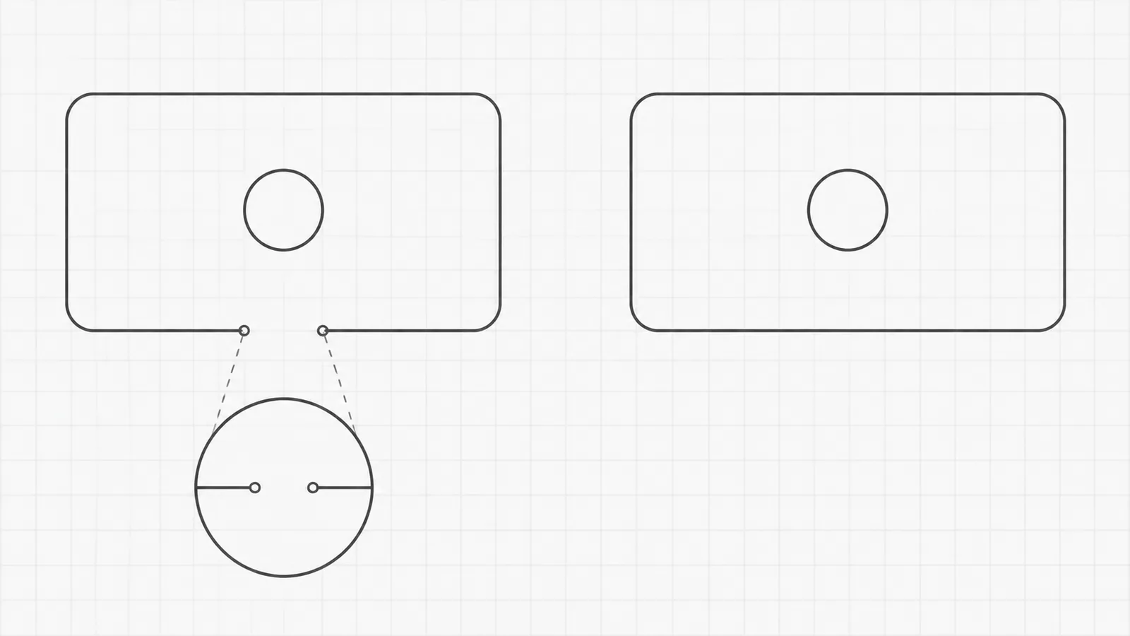
Imagine a rectangle with one side stopping a short distance before the neighbouring side. Viewed as part of a whole drawing, the rectangle looks complete. To the software, it may be separate lines with a gap between their endpoints. The program is not obliged to guess how that gap should be closed.
Not every open line is an error, however. Dimension extension lines, axes, bend lines and some marking elements may intentionally be open. First establish what is meant to be cut, then look for defects in the required contours. This lets you correct the real problem without damaging valid drawing elements.
Why continuity matters for a part boundary
A closed contour helps identify unambiguously where the part ends and the material to be separated begins. For a simple plate, this means the outer boundary and the separate closed boundaries of the holes. Production preparation software uses this geometry to recognise features and create operations.
If a required boundary is broken, automatic preparation may stop, request clarification or process objects differently from what the customer expects. The specific behaviour depends on the application and its settings. It is therefore wrong to claim that every gap will necessarily leave a metal bridge or cause one particular defect.
It is important to distinguish a geometric gap from an intentionally retained tab that holds the part in the sheet. A specialist may specify such tabs during cutting preparation. An accidental gap in the source drawing is not a reliable way to request one. If part retention is needed, agree it separately.
Where nearly invisible gaps come from
A gap can appear after trimming or extending lines, moving an individual segment, converting a curve or exporting between applications. Sometimes someone draws by eye without snapping to endpoints, leaving a small space. The connection looks convincing, but the coordinates do not coincide.
Another cause is a contour section on a different layer that is excluded from the selected operation. The line exists in the overall drawing but not in the set of geometry chosen for cutting. In that case, the shape does not necessarily need changing: first check layer purposes and object selection.
There can also be lines that coincide in a top view but lie at different heights in three-dimensional space. For a flat part, this may be an unwanted consequence of copying from a solid model. Do not immediately use a joining command with a large tolerance. First understand why the software does not recognise shared endpoints.
| Observation | Possible cause | What to check |
|---|---|---|
| An edge looks complete but is not recognised | Endpoints do not coincide | Coordinates and snaps |
| Everything is in the drawing, but selection introduces a gap | A layer or segment was omitted | The objects selected for cutting |
| Lines touch in top view | Different heights in space | The geometry's plane |
| A gap appears after export | Conversion or a missing element | The exported copy and source |
A methodical way to find the problem
Preserve the original and open a working copy. Initially, isolate the part geometry needed for checking, but do not delete other elements without understanding their role. Check scale, part count and layers: an open-contour warning sometimes concerns a construction line rather than a cutting contour.
Next, use an open-contour check or boundary creation tool if your application provides one. It may highlight endpoints or areas where the chain fails to connect. Command names differ, so focus on what they do rather than following a random sequence of clicks intended for another program.
Zoom into the suspicious area and inspect endpoint properties. Look not only for a visible gap but also for an extra short segment, an overlap or a segment ending slightly to one side. For a complex contour, check it in sections. This makes it easier to find the specific problem than endlessly zooming into the entire drawing.
Do not rely only on a fill or hatch. Some display or region creation tools can conceal small gaps according to their settings. A coloured shape on screen does not prove the objects selected for cutting are connected correctly.
Pay separate attention to self-intersections. A chain may close while crossing itself and creating an unwanted loop. This is a different error that a simple open-endpoint check may miss. After restoring a connection, inspect the whole contour and make sure it describes one clear boundary without accidental branches.
Do not confuse a displayed dashed line with physical gaps between objects. A line type can show continuous geometry as dashes simply to make the drawing readable. Conversely, several short solid segments can genuinely be separated. Examine the objects and their purpose, not only their display style.
If the part has several internal cutouts, check each separately. Repairing the outer edge does not automatically confirm that every hole is ready. Compare their number and positions with the control drawing, then inspect the complex areas. This is a short, meaningful check, not a redesign of the whole part.
Is setting the “closed” property enough?
In many systems, a polyline has a separate closed property. However, a closing command may do more than change a word in its properties: it may add a section between the last and first points. If those points are far apart or incorrectly located, the result will be a new, unwanted edge.
For example, a contour with a complex rounded section may have lost an arc. Automatically closing it with a straight segment can make it formally closed while replacing the flowing edge with a chord. The software stops complaining, but the part's shape no longer matches the intention. The disappearance of a warning is therefore not a sufficient check.
Both continuity and correct shape must be confirmed. When the intended contour is obvious and supported by dimensions, the correction may be straightforward. When the missing segment is unclear, return to the designer's model or drawing instead of inventing a connection.
Correcting a gap without changing the design
If two straight lines should meet at a specified corner, connect their ends according to the correct geometry. If an arc is missing, restore the required arc with the agreed radius. If a segment was accidentally moved, correct its position rather than extending neighbouring lines merely to hide the error.
Automatically joining nearby endpoints can help, but the operation's tolerance should not be chosen at random. An excessive value can connect the wrong points, particularly near narrow slots, small cutouts or neighbouring contours. A number that worked for another part does not become a general rule.
After correction, check overall dimensions, holes, radii and characteristic transitions. Compare with the original model or control drawing. The operation should restore the intended shape, not merely produce a successful check message. If dimensions or the outline have changed, that is a design change requiring agreement.
Example: a hole that appears closed on screen
Suppose a panel contains an elongated hole with two straight sides and rounded ends. After editing, one straight side stops slightly short of an arc. This is invisible at normal zoom, but the cutting preparation software reports an open chain.
In a working copy, locate the disconnected endpoints and compare the hole's length, width and radii with the drawing. If the shape is correctly specified and only the connection is wrong, repair it while preserving those requirements. Do not move the arc arbitrarily to “reach” the straight line: this can change the hole length or the rounded end's position.
Then check the whole hole, not just the corrected point. It should be closed, without extra segments or unwanted kinks. After export, reopen the file. Only then send the new revision to the manufacturer and explain what was corrected.
For this example, conformity to the intended design matters, not a universal gap size. Even a small correction must preserve the hole's function: fastening, adjustment or passage of another component. That is why automatic “close everything” cannot replace careful checking.
Why the file needs checking again after export
The source model and the transferred DXF do not always store geometry in the same way. Export may convert objects or change their structure. After correction, therefore, simply saving the model and assuming the manufacturing file is automatically correct is not enough.
Open the actual file you intend to send. Make sure the required contours are closed, units are correct, and unwanted layers are not included in cutting. If the manufacturer reports a problem in their own application, ask them to mark the exact location and identify the file revision used.
Do not send several almost identical versions without explaining which is final. This creates fresh uncertainty even when the gap has already been fixed. One current file, a revision number and a short note save more time than lengthy correspondence with repeated attachments.
What message will help the manufacturer?
Explain exactly what should be closed: the outer edge, internal holes or individual cutouts. If there are open marking lines or reference axes, state their purpose. This prevents the manufacturing specialist from “repairing” intentional features and lets them concentrate on the cutting contours.
Include material, thickness, quantity and a control drawing. For example: “Panel P‑22, revision 2. The straight-line-to-arc connection in the elongated hole has been corrected; dimensions remain as specified in the drawing. Open lines on the separate layer indicate bends only and are not for cutting.” This is concrete information that can be checked.
If you are uncertain about the geometry, do not conceal that behind “the file is ready.” It is better to submit it for assessment and identify the doubtful feature. The final correction should be agreed with the person responsible for the part's design.
Send a drawing for a manufacturing assessmentWhat a successful check means
A successful check is more than the absence of an open-contour warning. You need to know that each boundary intended to be closed is genuinely continuous and that its shape and dimensions meet the requirements. Reference and marking lines should retain their intended purpose.
For repeat orders, keep the corrected revision and a short description of the change. This helps prevent the old file from returning and avoids starting the same investigation from scratch. New geometry changes will still need review, but you will know which correct version is your starting point.
The main principle is to restore the correct contour, not simply close a gap. Checking the source, reopening the export and confirming the manufacturing version give a much more reliable result than attempting to fix everything with one automatic click.