

Why one visible line can actually be two
A drawing can show one visible line while the file contains two separate objects in exactly the same place. If both enter cutting preparation, the software may create an unnecessary operation. This is why it is worth checking a DXF for duplicates before handing it over: they can be invisible even in an otherwise tidy drawing.
There is an important qualification, however: a duplicate in the file does not mean the laser will necessarily pass over that location twice. Some applications detect redundant objects, others allow them to be excluded, and the result depends on settings and operation selection. Likewise, a repeated machine pass does not prove a duplicate caused it. Both the geometry and the prepared toolpath need checking.
For the customer, the practical task is simpler: supply a clean, unambiguous contour rather than asking the manufacturer to guess which overlapping line is correct. We will look at where duplicates come from, how to distinguish them from necessary geometry, and how to remove redundant objects without damaging the part.
Different kinds of overlap should not be confused
A complete duplicate might be two identical circles with the same centre and diameter. On screen they look like one hole. The object list may nevertheless contain two independent circles, each with its own layer or other properties.
Partial overlap occurs when only part of the lines coincides. For example, the long side of a rectangle may lie over a shorter segment. This is more complicated: deleting the entire long object can destroy the required contour, while simply joining objects without checking can change its structure.
There are also nearby but different lines. At a small display scale, the two edges of a narrow slot may look like one. They are not duplicates: the necessary distance between them defines the slot width. This is why automatic cleaning with an overly broad tolerance can be dangerous for small features.
| Situation | What the file actually contains | Appropriate action |
|---|---|---|
| Complete duplicate | Two identical objects | Keep the required object and check its properties |
| Partial overlap | A shared section of different objects | Examine the contour and preserve the required shape |
| Two nearby edges | Different boundaries of a narrow feature | Do not delete without checking its dimension |
| Cutting and marking together | Different operations at the same location | Clarify their purpose and operation selection |
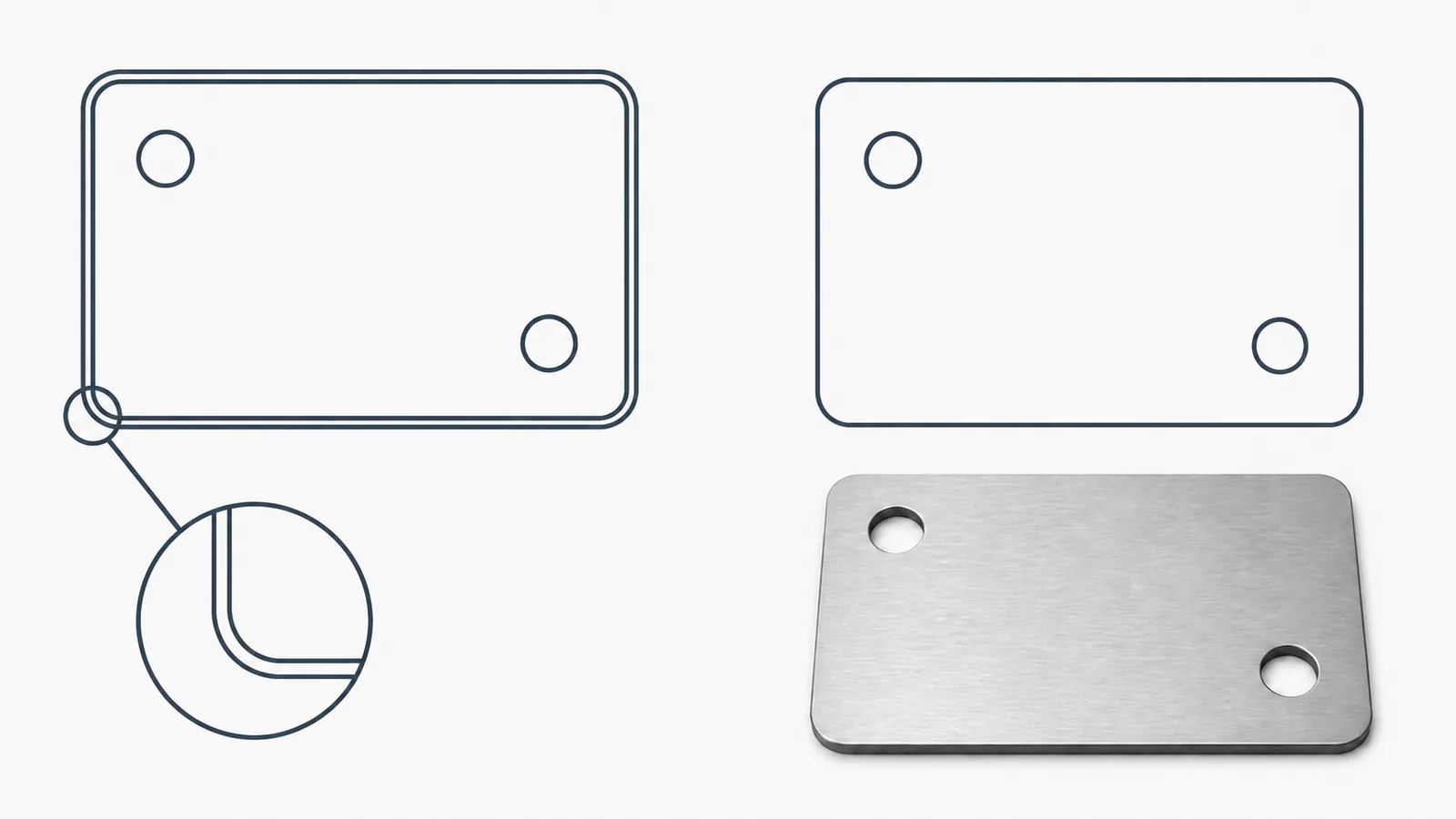
Where extra lines come from
The cause is often mundane: a contour was copied, but the copy remained in the same position. Or a block containing the required geometry was inserted into the file and then traced manually. A similar error occurs when several drawing versions are combined and old elements are not removed.
Overlapping layers are another case. A cutting line may coincide with construction geometry or an element for another operation. Everything looks normal until production preparation software selects both layers. Layer names and colours help people, but do not by themselves guarantee correct operation selection.
Nor should repeated export be treated as automatic cleaning. If a redundant object already exists in the source, it can travel into the new file. It is therefore useful to look for the cause in the editing history: what was copied, inserted, broken into pieces or combined before the problem appeared?
How this can interfere with manufacturing
The most obvious risk is an unnecessary toolpath. It may increase processing time and deliver energy again to an area already cut through. The consequences depend on the particular process: unwanted edge changes, local overheating or other deviations are possible. However, a DXF alone cannot predict the exact defect or prove that one will occur.
Problems can also arise before the machine starts. Overlapping segments may interfere with identifying closed contours, sorting holes and outer edges, or preparing the part automatically. The manufacturing specialist then spends time working out what the designer intended. For the customer, that means additional questions and a possible delay to the start of work.
Duplicates also complicate editing. Someone deletes or moves a line, sees another underneath and assumes the command failed. Further accidental changes then follow. A clean file is needed not only by the machine but by everyone who checks and reuses it.
Finding a suspicious area without starting the cutting process
Begin with a copy of the file. Preserve the original and use a separate revision for checking. Open all layers relevant to manufacturing and look for several overlapping versions of the part. Do not delete reference elements at random: first establish what they are for.
In a design system, you can select a line and inspect its properties, then use selection cycling through overlapping objects if that feature is available. Temporarily moving a suspicious object in a working copy can also reveal another underneath it. After diagnosing it this way, undo the movement or close the copy without saving the accidental change.
A built-in duplicate detection command often saves time, but its result needs to be understood. Know whether it compares geometry only, considers layers and other properties, or combines partially overlapping segments. The same command name in different applications does not mean identical behaviour.
Check geometry inside inserted blocks separately. Externally, a block may select as a single element while containing several contours. If another copy was drawn over the block, simply counting visible lines will not explain the problem. Understand the structure first, and change it only in a control copy followed by another check.
When several people have worked on a file, establish who is authorised to issue the final revision. Otherwise, one person may remove duplicates while another sends the old version again. This does not require an elaborate system: a clear revision number, one responsible person and confirmation of which file the manufacturer received are enough.
If the object count changes after correction, do not judge the result by that number alone. One polyline can replace several segments without changing the shape, while several segments can still be parts of one required contour. Check the holes, outer boundary and dimensions. Use object count as a clue for investigation, not as independent proof of readiness.
Cleaning the file without removing necessary geometry
If two identical cutting objects are found, keep the one with the correct properties. Do not choose it simply because it appears first in the list: one may belong to the required layer while the other is leftover reference geometry. After deletion, check that the line really remains where it should.
For partial overlaps, first establish the intended contour. Sometimes removing an extra short segment is enough; sometimes several connections need correcting. If the geometry is ambiguous, it is safer to return the question to the designer than to draw in an edge yourself. Cleaning should remove redundancy, not change the design.
Treat the setting that determines when nearby objects count as identical with care. Increasing it without reference to the part may affect a thin slot or another small feature. There is no universal value for every drawing. After an automatic operation, compare the result with the source and check critical dimensions.
Example: a rectangular plate with four holes
Imagine a plate with four mounting holes. One hole was copied several times, accidentally leaving two circles in one location. The image shows four holes, but the software may find five circles. This is a useful reason to check the file, although object count alone is not a substitute for analysis: contours can be represented in different ways.
In the working copy, check the centres and diameters of the suspicious circles, their layers and their intended purpose. If this really is a complete duplicate of one hole, remove the redundant circle. Then check all four diameters, the distances between centres and the overall plate dimensions. Cleaning an internal feature should not change the outer shape.
The manufacturer then reopens the updated file and checks the prepared operations. It is important to use the new revision rather than an old attachment from earlier correspondence. A clear filename and a short message such as “Duplicate hole removed; dimensions unchanged” make the handover understandable.
Why the toolpath still needs checking after cleaning
Correct geometry is the foundation, not a finished machine program. In cutting preparation software, check which objects are selected for the operation, which contours will be processed and whether there is unnecessary repetition. This should be done by the specialist responsible for production preparation.
A preview may show repeated movement, but it is important to distinguish tool movement from cutting with the beam active. Travel between areas, approaches or deliberately specified operations should not automatically be called duplicates. Examine the purpose of the particular toolpath section.
Similarly, a shared edge between two neighbouring parts may belong to a deliberately arranged cutting layout. That is not a reason to delete a side from the source drawings yourself. Common-line cutting needs appropriate preparation and agreement, while individual part files should remain clear and reusable.
What to send the manufacturer after correction
Send one clearly identified current file and explain what changed. If only duplicates were removed, say that the intended geometry is unchanged. If cleaning required a contour correction, agree it as a drawing change rather than concealing it under the label “technical adjustment.”
Keep the control drawing, material, thickness, quantity and revision number with the file. Ask the manufacturer not to use the previous copy. For a repeat production part, retain a short note about the reason for the correction so the next person does not restore old geometry from an archive.
If you do not work professionally with drawings, describe the concern and supply the source for checking. There is no need to experiment by deleting unfamiliar objects from the only copy. A clear question such as “Are there overlapping cutting contours here?” helps start the check with a specific problem.
Send a drawing for a manufacturability assessmentHow to avoid returning to the same error
Before each new export, check for hidden copies and construction objects left behind. Pay particular attention after combining drawings or inserting blocks. For recurring orders, keep a short sequence: source check, export, reopen, dimensional check and confirmation of the manufacturing revision.
Do not judge a file's cleanliness only by how good it looks on screen. Two objects can look like one, while two necessary edges can almost coincide. The best result comes from combining property checks, search tools and careful comparison with the part's intended function.
The conclusion is simple: remove confirmed redundancy, not everything that looks similar. After cleaning, the geometry must remain correct, and the manufacturer should check that the program uses it without unwanted repetition. This reduces the risk of rework without replacing drawing verification with assumptions about machine behaviour.