

How to make sure the part cut from your DXF has the right dimensions
To receive a correctly sized part, writing “everything is in millimetres” in an email is not enough. The coordinates in the file, the units used when opening it, and the dimensions on the reference drawing must all mean the same thing. The simplest check is to reopen the actual exported DXF you intend to send, measure an overall dimension and another distinctive feature, then ask the manufacturer to verify those dimensions after importing it.
Imagine a mounting plate 240 mm long. On screen it looks like an ordinary rectangle with four holes. But the software can show the same-looking rectangle for a length of 24 mm or 2400 mm: it simply fits the image to the window. A visually correct shape does not yet confirm the correct physical size. That is why a units error is better found by measurement than by comparing the picture with your memory.
The good news is that you do not need to understand the entire DXF structure or know how to program a laser cutting machine. You only need to distinguish a few concepts and send the file with short, unambiguous information about the part.
What drawing units actually mean
Geometry in drawing software is defined by numbers. The distance between two points might be 100. To turn that number into a real length, you need to know what one unit represents: a millimetre, centimetre, metre or inch. Millimetres are often used for sheet-metal parts, but the DXF format does not automatically mean that every file received should be interpreted that way.
A DXF can contain information about units. However, the receiving software may use its own import settings or ask for the unit separately. Behaviour also depends on how the file is inserted: opening a drawing and inserting it as a block in another drawing are not necessarily the same operation. Recording units in the file is therefore useful, but does not replace checking the result in the recipient’s software.
There is another important trap: changing the unit label does not always change the geometry. If a line had a numerical length of 10 and you only changed the setting from centimetres to millimetres, the software might leave the number at 10. Alternatively, it might offer to convert it to 100. Before confirming, understand whether only the interpretation of the numbers changes or the object coordinates change too. Measuring afterwards gives a more reliable answer than the setting’s name.
Why print scale is not the scale of production geometry
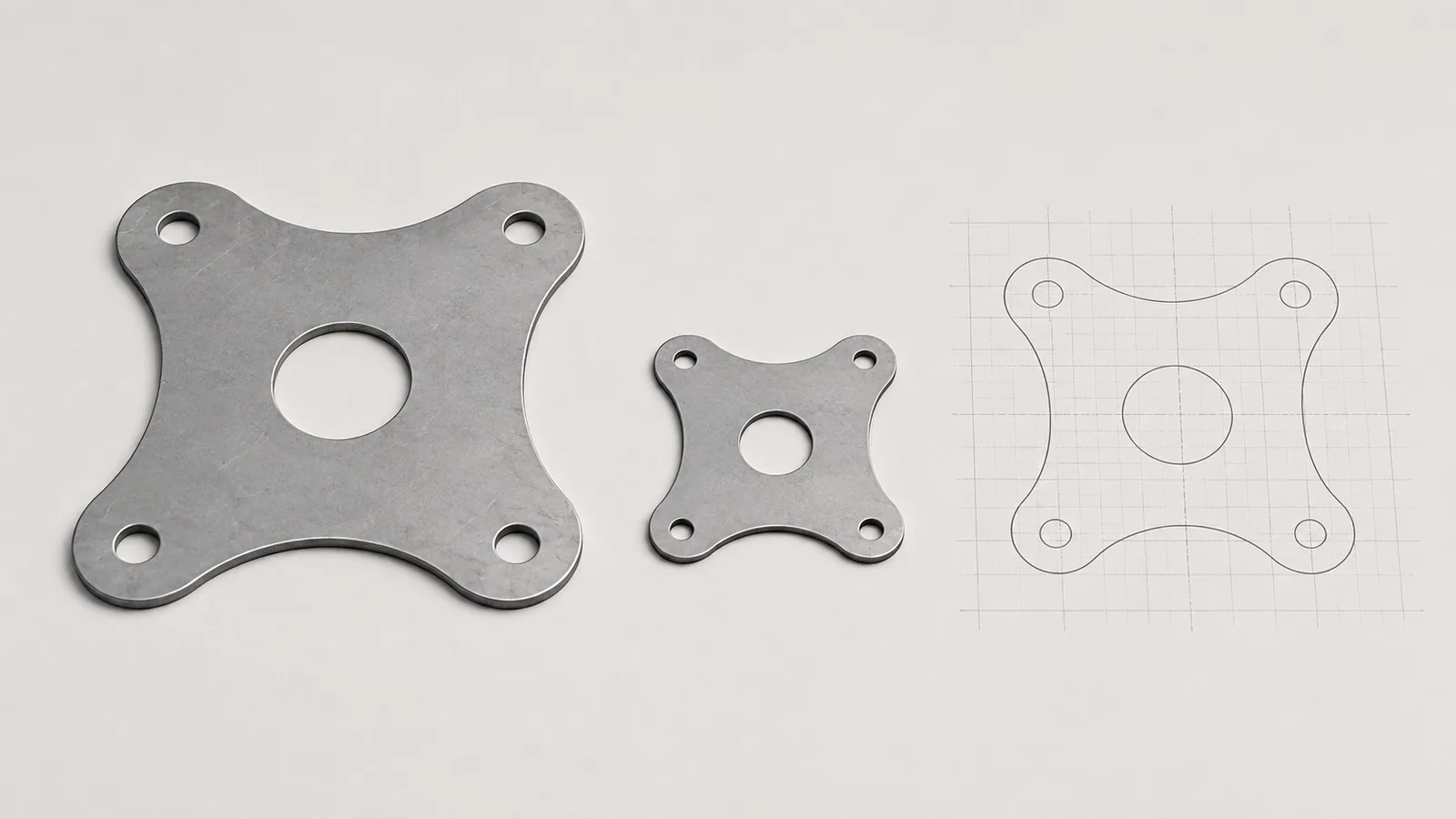
On paper, a large part may be shown at 1:2 and a small assembly at 2:1. This helps fit the image on the sheet and keep it readable. The stated dimension still describes the real part, not the length of the line you would measure with a ruler on the paper.
Production geometry for cutting is normally supplied at full size, meaning 1:1 in the agreed units. Do not halve the actual contour simply because the drawing sheet is presented at 1:2. View or print scale and model dimensions serve different purposes.
For example, a plate is 240 mm long. In a PDF printed at 1:2, it occupies 120 mm, but measurement in the production DXF should show 240 mm. If you exported reduced graphics from the sheet instead of the part geometry, the recipient may receive exactly 120. Before exporting, establish what the software is saving: the model, a sheet-metal flat pattern, or a formatted view with a border and dimensions.
What the size of the error can tell you
The ratio between expected and received dimensions helps identify the cause, but is not permission to scale the whole file immediately. Check several features first: have they all changed equally, or does the problem affect only an inserted fragment?
| What appears after import | Possible explanation | What to check |
|---|---|---|
| 24 mm instead of 240 mm | Centimetres read as millimetres, or a factor of 0.1 applied | Original units and export settings |
| 2400 mm instead of 240 mm | Reverse unit conversion or unnecessary enlargement | Whether conversion was applied twice |
| Dimensions differ by a factor of 25.4 | Confusion between inches and millimetres | Model and import units |
| Overall dimensions are correct, but one group is too large | An individual block was inserted at a different scale | Properties of that particular block |
| Length is correct, but width is wrong | Non-uniform scaling or a different geometry revision | Both coordinate axes and the file version |
The number 25.4 has an exact explanation: one inch equals 25.4 mm. However, a similar ratio alone does not prove where the error occurred. For example, a file may have been correctly converted to millimetres and then had the same factor applied again during import. Fixing the cause in the transfer chain matters; otherwise the next revision of the part will be wrong again.
Which reference dimensions to choose
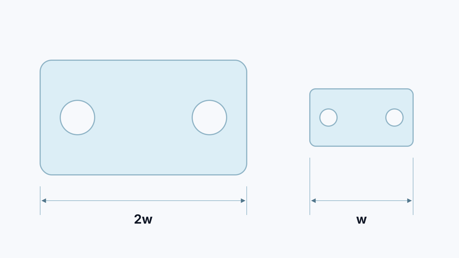
For a simple flat part, it is convenient to check length, width, and the diameter of one hole or the centre-to-centre distance between two holes. This does not replace a complete drawing inspection, but quickly reveals an overall scale change and some local errors. A single overall dimension will not show that a separately inserted group of holes has remained in different units.
Choose dimensions with unambiguous measurement points. “Approximately 200 mm along the long side” is less useful than “the distance between the left and right outside edges is 200 mm.” For holes, specify whether the distance is between centres or edges. Do not invent a tolerance simply for a scale check: allowable variation in the finished part must come from the drawing and the agreed requirements.
A dimension label is not always evidence either. A drawing’s displayed number can be edited manually without changing the line itself. Use the measurement tool to check the geometry rather than simply reading the text beside the dimension line. If the label says 200 but measurement shows 180, return to the source model and establish which information is correct.
How to prepare and check the file before sending it
Start with the working model whose dimensions have already been defined. Check document units, overall dimensions and the properties of inserted blocks. If the part will be bent, agree who is responsible for the flat pattern: the finished three-dimensional model and the flat cutting contour are different representations. Correct scale does not fix an incorrect bend allowance.
Export the required geometry to the agreed DXF version. Do not use an arbitrary older copy simply because it opens without a warning. Keep the part designation and revision in the filename or accompanying specification. If the manufacturer requests particular export settings, apply them to this order rather than declaring them a universal rule for all software.
After saving, close the exported file and reopen it. Check the export itself, not the source model, which may still be correct. Measure the selected features, inspect the contours and ensure that required geometry has not disappeared. If possible, open the file in a different program from the one that created it. This is a useful additional exchange check, although import into the production system provides the final confirmation.
What to tell the manufacturer when sending a DXF
The accompanying information does not need to become a long technical instruction. Its purpose is to remove ambiguity. State the part designation, revision, unit, material, thickness and quantity. Add a reference drawing or PDF with the principal dimensions and identify which file contains the cutting geometry. Do not leave the recipient several similarly named versions and ask them to choose the latest one.
For example: “Plate K-12, revision 03. DXF geometry in millimetres, 1:1. Overall dimensions 240 × 80 mm; reference hole diameter 8 mm. Material and thickness according to the specification for this revision. Please verify these dimensions after import before preparing the quotation.” This is an example of transferring information, not a ready-made specification for every part.
If you are unsure, send the model and reference drawing to discuss order preparation. Clarifying units at the quotation stage is better than receiving a neatly made batch that is unusable because of its dimensions.
Discuss preparing your part for manufactureWhat to do if the manufacturer sees the wrong size
Ask for the actual measured dimension, the import unit and the exact file being used. Do not start with “make everything ten times bigger.” First compare revisions and check whether the same ratio applies to overall dimensions, holes and their spacing. If only part of the drawing differs, global scaling will damage the correct elements.
Once the cause is confirmed, correct the settings or geometry in the source document and issue a new agreed file. If the manufacturer performs the conversion, approve the result and retain a record of the version used for production. Otherwise, a repeat order may involve sending the old file again and reintroducing the same error.
Repeat the reference measurements after the correction. Separately confirm that the shape, hole count, part designation and other requirements have not changed. This is a short but complete cycle: identify the cause, correct it, check it and supply one current version.
What correct scale does not prove
A file with correct overall dimensions is not automatically ready for production. It may still contain duplicates, gaps, unnecessary dimension lines or contours unsuitable for the selected operation. A units check answers only “how large is this geometry?”, not “has it been designed correctly and how should it be manufactured?”
Likewise, the number of decimal places in the software does not establish laser-cutting accuracy. Seeing 240.0000 on screen is not a promise of equivalent precision in the finished plate. Dimensional requirements and inspection methods are agreed separately, taking the material and process into account. Keeping these questions distinct avoids overloading a scale check with expectations while missing the actual part requirements.
A scan of a paper drawing or a photograph does not allow the same verification as a vector model. Scanning, printing or taking a photograph can stretch the image, while perspective changes proportions. If a contour is reconstructed from an image, one known dimension is not enough to trust all the others. The geometry must be defined again from dimensions and confirmed with the part’s designer. Tracing an image creates a new model; it is not merely correcting units.
Check old files from another contractor particularly carefully. They may have been prepared for a particular importer, contain scaled blocks or already incorporate manufacturing changes. Obtaining a confirmed source model and reference drawing is more straightforward than gradually adapting an unknown file. If no source model exists, tell the manufacturer explicitly. Verifying correspondence then becomes a separate agreed task rather than a hidden assumption when starting the order.
A short DXF scale-check sequence
- Agree the physical unit of the geometry: for example, one numerical unit represents one millimetre.
- Do not apply print scale to the production contour.
- Check both overall dimensions and a distinctive internal feature.
- Open and measure the actual exported DXF.
- Supply a reference drawing and one unambiguous file revision.
- Ask for confirmation of dimensions after import into the production software.
Reliability comes not from complicated documentation but from agreement between three things: what you designed, what you saved in the file and what the manufacturer opened. Once that agreement is checked numerically, a scale error stops being an unpleasant surprise in the finished part.