

How to tell the manufacturer which lines should be cut
A laser-cutting drawing must clearly separate the part contours from annotations that only help a person read the document. Layers are a convenient way to do this: cutting geometry separately, agreed marking separately, and construction lines separately. But dividing objects into layers does not by itself guarantee the correct program. The manufacturer must know the purpose of each layer and check that the right objects enter the right operation after import.
Imagine a plate with four holes and a part-number label. The screen also shows dimensions, centre lines and a drawing border. To the designer, this is a clear drawing. To manufacturing preparation software, it is a collection of geometric objects. Without an explanation of their roles, the label could become a through-cut, a centre line an unwanted cut, or an important mark could simply be left out of processing.
A well-prepared file therefore does not necessarily have many layers. It has enough layers to distinguish the tasks unambiguously, plus a short explanation of how to use them. The aim is not to complicate the drawing, but to remove the need to guess.
What a layer is and what it does not do
Think of a layer as a separate transparent sheet over the drawing. One sheet carries the part contour, another the dimensions, and a third the annotations. In the software, these groups can be displayed, hidden, selected or processed separately. A layer normally also has a name and display properties, such as colour or line type.
However, a layer is not a universal machine instruction. The name “Marking” does not itself set up the laser or guarantee a shallow mark instead of a through-cut. The production preparation system must associate that geometry with the appropriate operation. This association may already be configured at the company or established when preparing the specific order.
Colour is similarly convenient for inspection, but is not a sufficient instruction on its own. A red line might mean cutting in one production process and reference geometry in another. Unless you have agreed the convention, “cut the red lines” leaves too much dependent on display and import settings.
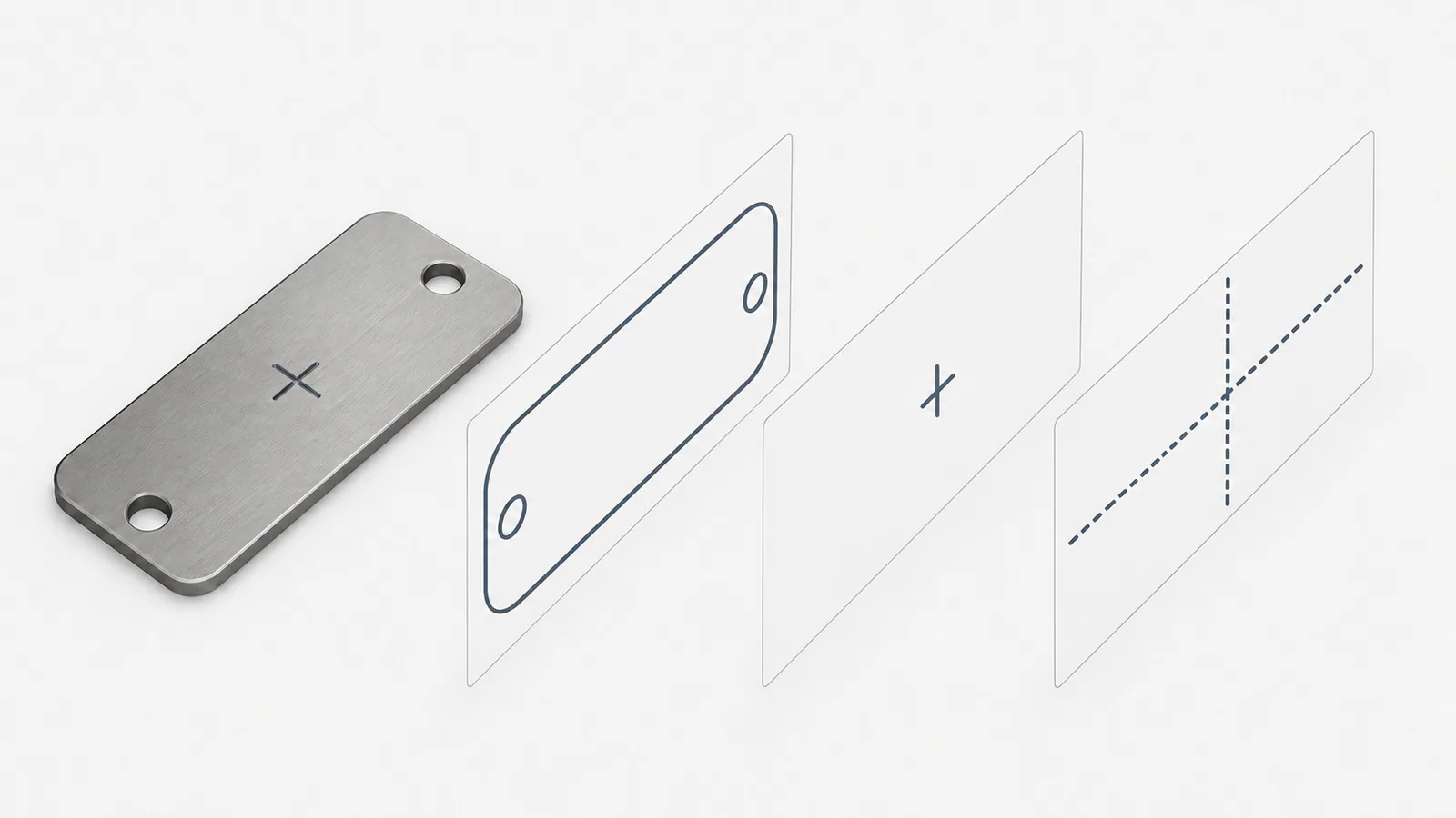
The three principal geometry groups
For most simple orders, start with three roles. The first is contours defining the outside shape and through-holes. The second is marking geometry, if marking is actually required and agreed. The third is information for reading the drawing that must not become a machining path.
| Role | What belongs in it | What needs agreement |
|---|---|---|
| Cutting | Outside boundary, holes, slots and cutouts | Which contours must form the finished part |
| Marking | Part number, assembly identification and agreed marks | Application method, side and required result |
| Reference information | Dimensions, centre lines, border, hatching and explanatory text | Exclusion from processing or supply in a separate document |
This is an example of logical grouping, not mandatory layer names for every manufacturer. If the company requests a cutting-only file on one layer and marking separately, follow that requirement. The correct handover is an agreed method that preserves the order’s meaning, not the largest possible number of drawing layers.
For a part that will be bent after cutting, bend lines may also be needed. They describe a subsequent operation, but do not mean the sheet should be cut through along the bend. Agree their delivery separately: on a dedicated layer, in a drawing or in a three-dimensional model, depending on the manufacturer’s workflow.
Example: a plate with a number and four holes
Suppose you need twenty mounting plates. Each has a rectangular outside contour, four mounting holes and the designation “K-12” to help the assembler. The working drawing also shows centre-to-centre dimensions and symmetry axes.
The cutting group should contain the outside contour and four holes. “K-12” belongs in the marking group only once its application method is agreed. Dimensions and centre lines can remain in a separate reference PDF so they do not interfere with geometry selection in the production file. The border and title block are also for a person, not the laser.
Inspect the groups separately afterwards. With only cutting visible, you should see the part shape without unrelated lines. With only marking visible, you should see just the required number or marks in the correct position. If one of the four holes disappears during this inspection, you have already found a problem: it was assigned to the wrong group. This is much easier to correct before sending the file than to explain after the batch is made.
Why text needs special attention
Text in a drawing can remain a text object or be converted into letter outlines. Both look similar to a person, but behave differently when transferred between programs. A text object can depend on an installed font. Outlines are already geometry, but the software must still know what they are for.
Converting a label to outlines does not automatically make it marking. If the letter outlines enter a through-cutting operation, the result will be entirely different. A stencil inscription also needs its enclosed letter interiors to remain attached. That is a question of inscription design, not simply a layer’s colour or name.
Before sending the file, agree whether the manufacturer accepts text objects or requires geometric outlines, and exactly what result is ordered. Specify the application side, position and legibility requirements. Do not independently assign laser power or speed just to explain the desired appearance: the operator determines manufacturing parameters for their equipment and material.
How to explain layers without lengthy correspondence
A short list of the actual layer names and the action for each is enough to accompany the file. For example: “Contour — through-cutting; Identification — agreed marking; Dimensions — reference only.” The names in the explanation must match the names in the file. If the DXF uses Latin-character names because of software requirements, they are acceptable technical identifiers, but their purpose still needs a plain-language explanation.
Also state the part designation, revision, material, thickness and quantity. For marking, clarify whether it is identical across the batch or changes for each part. “Apply the number” does not explain whether this means the drawing number, a serial number or an assembly position.
If you do not know which delivery method the contractor supports, send the reference drawing and describe the required result. This allows the file structure to be agreed before final preparation rather than reorganising every layer after the quotation.
Discuss your drawing and order preparationWhat to check after import into production software
The final check concerns not screen colours but the geometry selected for each operation. Cutting must contain every required external and internal contour. Marking must contain only the agreed identification. Reference information must not create toolpaths. If the system does not support the supplied separation method, resolve that before starting the order.
It is useful to verify the number of repeated features: for example, four holes, two slots and one number. Then check their positions and overall dimensions. Layers and scale are related only in that both need checking after import: correct geometry separation does not prove correct units, and vice versa.
When an error is found, the correction must remain in the current file, not only in the operator’s memory. Otherwise, the next batch begins with the same misunderstanding. Retain the agreed revision and briefly record what changed: for example, a hole moved from the reference layer to cutting, while dimension lines were moved to a separate PDF.
Common mistakes that are easy to avoid
The first mistake is assuming a layer name needs no explanation. Internal abbreviations from your project may mean nothing to another company. The second is supplying all working variants in one DXF: the manufacturer should not have to guess which overlapping contour is final. The third is trusting colour more than checking which objects are actually selected.
Another mistake is including everything that makes a drawing attractive in the production contour. Hatching, arrows, leaders and a border can be appropriate in a readable document but are unnecessary as cutting geometry. Separating the reference drawing from the production file often makes both clearer.
At the same time, do not clean a file so aggressively that important information disappears. Bend lines, the marking side or a special edge requirement may be essential to the order. Rather than simply deleting them, supply them in an agreed form that does not create an unwanted path.
For repeat orders, agree a simple handover template once. Keep the working layer names, a reference-drawing example and the revision-identification rule in it. The next part may have a different shape, but the way you explain its geometry will remain familiar. This is more useful than inventing new abbreviations every time or expecting the recipient to adapt to the author’s personal colour choices.
However, a template does not remove the need to check the specific file. If bending or variable marking is added to a standard plate, the order has a new operation. Describe it even if all the old layers remain unchanged. The best structure is one you can quickly explain to another person and verify in the result, not merely one that has been used before.
Signs of a clear cutting file
- Each geometry group has an unambiguous purpose.
- Layer names match the accompanying explanation.
- Cutting, marking and reference elements are not mixed.
- Text and bend-line delivery methods are agreed.
- The actual operation objects are checked after import, not just their colour.
- Production uses one current revision.
Well-organised layers act like a clear conversation between design and manufacturing. They do not replace the technologist, but help them understand your intent faster. They also give you a simple way to check that the future part will match the drawing rather than a random collection of visible lines.