

Which line is best suited to cutting?
A straight line is the natural choice for a straight edge, a circle for a round hole, and an arc for a section with a constant radius. A complex flowing outline can be supplied as a spline or an agreed polyline representation. However, the name of a geometric object does not by itself guarantee correct cutting. What matters is that the manufacturer's software reads the file without changing the shape and that the prepared toolpath matches the drawing.
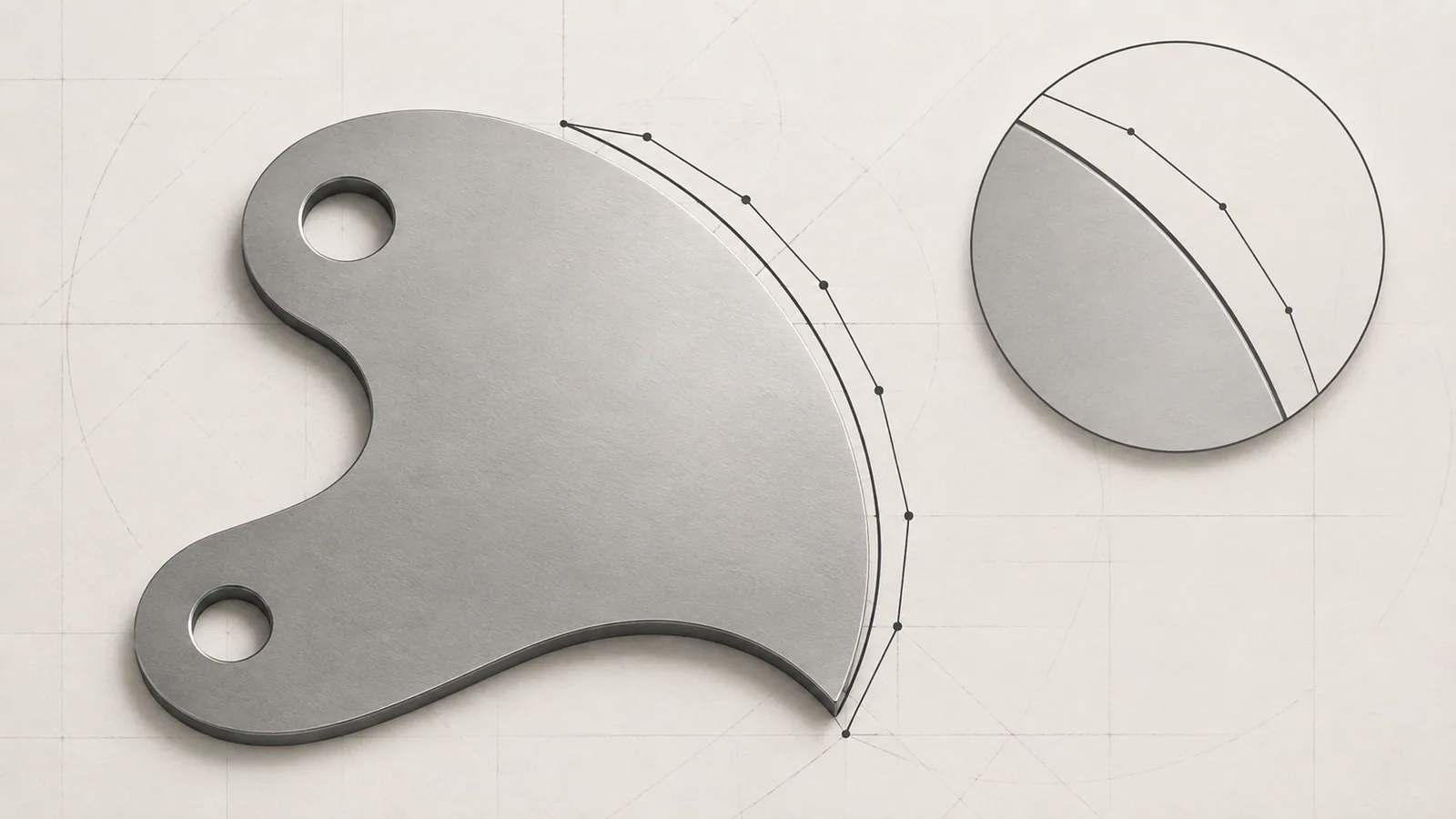
Imagine a decorative panel with a wavy edge. The wave looks smooth on the designer's screen and still appears smooth in another application. Zooming in, however, reveals dozens of short straight segments. That is not necessarily a defect: an accurate enough approximation may be perfectly suitable. The problem starts when the deviation is visible on the finished part or affects how it connects to another part.
The right question for the manufacturer is therefore not “Do you accept splines in general?” but “Will the required shape of this part survive your production preparation process?” Let us look at what that means and how to check a file without specialist knowledge of machine programming.
Lines, arcs, polylines and splines in plain language
A straight line defines a segment between two points. An arc describes part of a circle, while a circle is a closed round contour. If a hole is meant to be round, keeping it as a circle is usually more logical than assembling it from many straight segments. This makes it easier to check its diameter and preserve the intended shape during editing.
A polyline combines several sections into one object. It does not necessarily consist only of straight segments: some representations can also contain arc segments. The word “polyline” therefore does not automatically mean “a jagged line with corners.” You need to examine what it contains and what remains after export.
A spline describes a smooth curve whose shape can change in more complex ways than a circular arc. It is useful for designed outlines, transitions and surfaces that cannot be built from simple radii. You should not turn every spline into an arc merely to simplify a file: doing so may change the part.
| Object | Useful for | What to check after transfer |
|---|---|---|
| Straight line | A straight side | Length and endpoint positions |
| Circle or arc | A hole or specified radius | Diameter, radius and connections |
| Polyline | A single contour made of several sections | Closure and segment composition |
| Spline | A complex smooth outline | Shape and accuracy of any conversion |
Why a correct drawing can change on its way to the machine
A part is usually created in a design system and then exported, for example, to DXF. The manufacturer opens that file in cutting preparation software, often called CAM. There, the geometry is used to build manufacturing operations before a program is produced for the particular equipment.
Conversion can occur at every transfer. One system keeps a spline as a spline, another approximates it with short segments, and a third may offer a combination of arcs. Different format versions and export settings can also produce different results. This does not necessarily mean an application is poor: it may simply expect a different representation of the data.
For the customer, checking the final geometry matters more than the format's name. Saying “We sent a DXF” does not confirm that every curve was read correctly. An agreed export method and a control file that the manufacturer has actually opened and checked are more useful.
What curve approximation means and why there is no single correct number
Replacing a complex curve with simpler sections is called approximation. Imagine reproducing a smooth wave using short rulers. The more appropriately the lengths and positions of those segments are chosen, the closer the new contour is to the original. But the number of segments alone does not measure accuracy.
An overly coarse conversion may create visible facets, change a narrow section or prevent parts from fitting together. An excessively detailed file can make data processing more cumbersome without adding the quality the product needs. Equally, segment count alone cannot predict cutting speed: toolpath preparation, machine control and other conditions affect movement.
The permissible deviation should reflect the part's requirements. Appearance matters for a decorative outline, while agreed dimensions and tolerances matter for a mating contour. Do not copy an arbitrary accuracy setting from instructions for another program. First decide what must be preserved, then choose and verify the conversion.
Which areas should be checked first?
Not every part of a contour is equally sensitive to a change in shape. Pay particular attention to holes, mating areas, narrow webs and transitions between straight and curved sections. A small geometric deviation may matter more there than along a long, unrestricted edge.
Check whether an intended smooth transition really remains smooth. Two lines may meet at their endpoints yet form an unwanted kink. Conversely, a neat picture at normal zoom does not prove their endpoints coincide mathematically. A closed outer contour should not turn into a chain with a barely visible gap.
If the drawing specifies a radius, check the radius itself rather than only the similarity of the pictures. If the shape is defined by an electronic model without a simple dimensional description, agree with the manufacturer which model is the reference. This avoids a situation where each participant is looking at a different “correct” version.
Example: a panel with a flowing edge and mounting holes
Suppose you need a panel with a wavy outer edge and four mounting holes. The wave determines its appearance, while the holes must align with holes in the frame. For this part, it makes sense to check the decorative contour and the mounting geometry separately.
First preserve the original model. After export, reopen the resulting DXF and check the overall dimensions, hole diameters and distances between hole centres. Then zoom into the tightest parts of the wave: coarse approximation is often more noticeable there. If your software can compare contours by overlaying them, use that feature, but also check the critical dimensions.
Tell the manufacturer that the holes are functionally important and the edge needs the agreed smoothness. This is not a request to “make it look nice however you think best”: the required result should be described by a drawing, tolerances or an agreed sample. For an expensive or unfamiliar part, trial manufacture may be a sensible way to check the entire sequence.
A file preparation sequence that avoids unnecessary rework
Start with the source model, not a random copy passed between applications several times. Make sure it contains no unnecessary lines, duplicate objects or unwanted three-dimensional geometry. For a flat part, the manufacturer needs to know unambiguously which two-dimensional contour to use.
Next, confirm the accepted export format and version. If the manufacturer asks you to convert splines, ask how the resulting accuracy will be checked. Do not immediately change all curves in the original. It is better to create a separate manufacturing copy, perform the conversion and compare it with the source.
After saving, close the file and reopen the actual exported version. Check scale, part count, holes, contour closure and characteristic transitions. Then ask the manufacturer to confirm the import. If there is an error, discuss the specific location rather than a general impression that “the file is unsuitable.”
Another useful step is to request a view of the imported part with control dimensions marked. It can quickly reveal an obvious misunderstanding: a different scale, a missing hole or the wrong revision. However, a screenshot is not a substitute for an accuracy check. Displayed line thickness and zoom can conceal deviations that matter during assembly.
If the software reports an unsupported object, retain the message and identify the affected area. There is no need to redraw the entire part immediately. Sometimes changing the export method for one element is enough; sometimes the source model needs clarification. In both cases, check the final file again, because opening successfully without a warning does not prove the geometry is correct.
For parts that mate with each other, assess the two surfaces together. The accuracy of one outline does not guarantee assembly if the matching part has a different revision or was designed for a different clearance. Tell the manufacturer what the joint is for: free installation, positioning or subsequent welding. This helps raise the right drawing questions without replacing a design decision with an arbitrary software setting.
What to send the manufacturer with the DXF
A short accompanying message should identify the part and revision, units, material, thickness and quantity. Highlight critical areas and include a clear drawing for dimensional checks. If you have already converted curves, say so, to prevent another unnoticed conversion by the manufacturer.
For example: “Panel P‑14, revision 3, dimensions in millimetres. Check mounting holes and their positions against the drawing. The outer outline was exported from a spline; preservation of the shape must be confirmed before manufacture. If another geometric representation is needed, please request a revision.” That is more useful than a long list of application names without an explanation of what matters for the part.
You do not need to prescribe cutting parameters or control command types to the manufacturer. Your responsibility is to supply unambiguous geometry and product requirements. Toolpath preparation and the choice of manufacturing settings belong to the production process.
Send a drawing for a manufacturing assessmentThree mistakes that should not be corrected by guesswork
The first is converting every object into short straight segments “for compatibility.” A particular process sometimes requires this, but it is not a universal improvement. A circle that can be represented accurately does not necessarily need to become a polygon. Establish the importer's actual requirements first.
The second is joining segments without checking the shape. A join command can help organise a contour, but it does not make incorrect geometry correct. After any automatic repair, check dimensions, connections and the number of separate contours again.
The third is fixing only the manufacturing copy and forgetting the source drawing. A repeat order can then reintroduce the old error. Changes that affect the part's shape must be agreed and saved in the coordinated revision. The correction history is especially important when the part must fit assemblies that have already been made.
How to know the geometry is ready to hand over
A finished file does not have to contain only one line type. It should describe the intended part unambiguously, open in the agreed process, and preserve critical dimensions and shape. After checking, it should be clear where the outer edge and holes are, which contours are closed and which revision is current.
For regular orders, retain verified export settings and a short checklist. Even a familiar template does not eliminate the need to check a new complex curve or a change of software. Comparing the file for a few minutes before production is usually easier to arrange than finding out afterwards why a smooth outline has changed.
The main principle is simple: choose geometry to suit the part, and confirm compatibility through the import result. There is no need to fear splines or trust polylines unconditionally. You need to make sure the manufacturer cuts the shape you actually intended.