

Press-brake axes are specific motions, not a score of capability
The usual names are straightforward: Y or Y1/Y2 move the ram and punch; X sets how far the sheet edge is fed to the backgauge; R changes backgauge-finger height; and Z1/Z2 move those fingers along the length of the sheet. Manufacturers do not always count the same motions in their total, so “seven axes” alone does not describe what a machine can do.
The better buying question is: which manual actions should disappear on my parts, and which will remain? A basic configuration can be right for repeated brackets and simple boxes. R, Z1 and Z2 become useful when parts are long, asymmetric or already have formed returns.
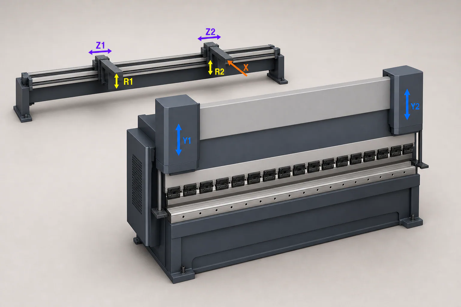
- Y1 / Y2Ram motion
- X, R, ZRear backgauge
Y, Y1 and Y2: how the press forms the bend
Two different systems work on a press brake. At the front, the ram carries the upper tool, the punch, and creates the bend. Behind the bend line sits the backgauge. Its fingers receive the sheet edge and establish the flange dimension. The sheet contacts the fingers, not the long beam or rail that carries them.
This is where most confusion starts. Y does not move the sheet across the table, and X does not form the angle. Y/Y1/Y2 belong to ram motion. X, R and Z1/Z2 belong to the backgauge. The CNC coordinates those motions but is not another mechanical axis.
The next view shows where both backgauge fingers physically sit. It is a map of the two systems: a front view makes Y1/Y2 easy to recognise, while X, R and Z have to be read on the rear mechanism.
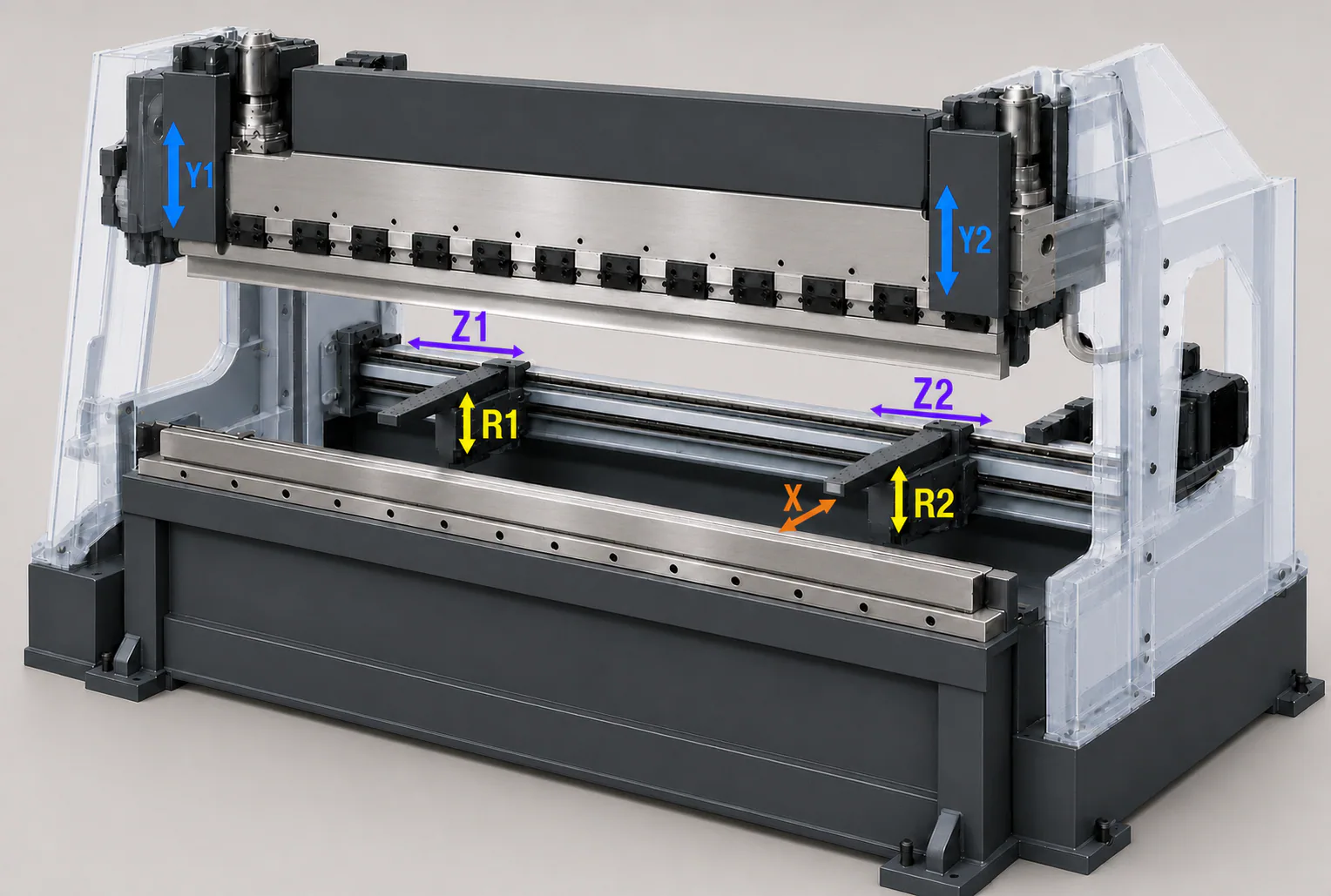
- X, R, ZBackgauge motions
Y is the programmed vertical position of the ram: how far the punch enters the die for a particular bend. On many machines, the left and right sides of the ram are controlled separately as Y1 and Y2.
That does not mean an operator controls two sides by hand. The CNC synchronizes the ram to the programmed position. Separate control matters for ram motion accuracy, but it does not cancel the effect of material thickness and strength, tool condition, bend length or crowning.
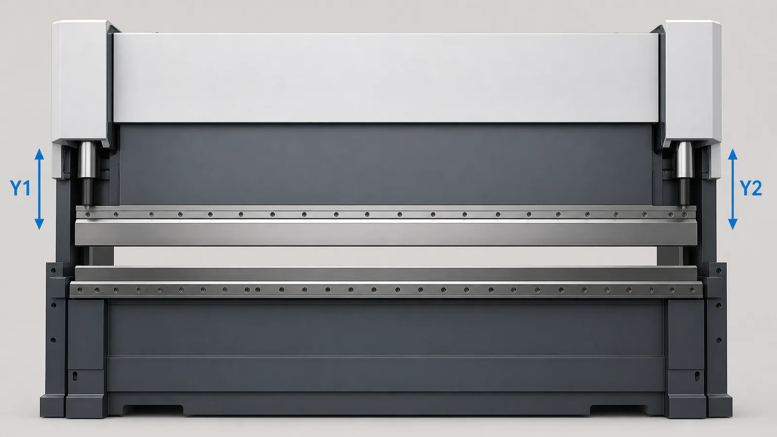
- Y1 / Y2Ram synchronisation
X: the axis that most often sets a flange size
When a sheet is fed into the press, its edge touches the backgauge finger. The distance from that edge to the bend line becomes the future flange. X moves the backgauge forward and backward to set that distance.
For repetitive parts, X is one of the most useful axes because it removes repeated manual marking. It does not inspect the finished part in place of an operator; it only returns the sheet to a programmed reference. During a demonstration, look at the full cycle: whether the gauge retreats from a formed return, reaches the next position and has enough travel for the deepest flange.
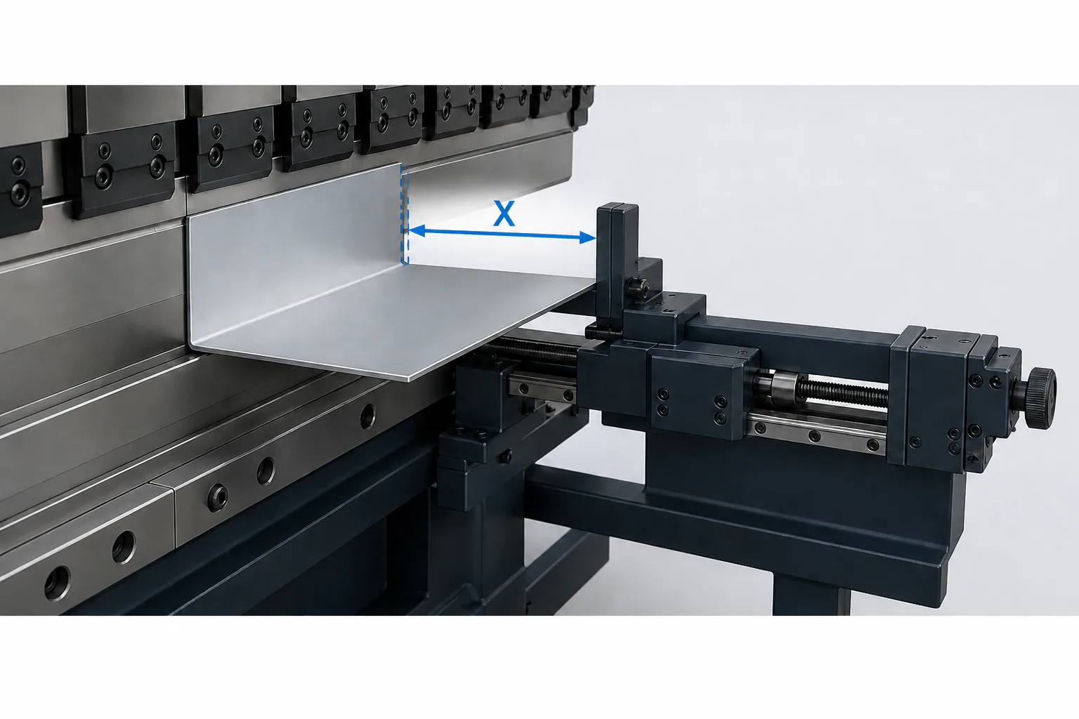
- XDistance to bend line
R: when a backgauge finger also needs height
Sometimes the finger must do more than stand at the correct X depth. A previously formed return may sit above or below the point where the part needs support for the next bend. R raises and lowers the backgauge finger.
R is useful only in a real bending route. If every part can reference the same flat edge, it may have little effect on daily work. If operators must flip a part, reset fingers or search for another support point because of a formed return, R can remove those repeated actions.

- RBackgauge finger height
Z1 and Z2: where the fingers stand along the sheet
A backgauge normally has at least two fingers. Z1 and Z2 move them left and right along the machine length. Do not confuse this with X: X sets depth to the bend line; Z sets the lateral positions of the support points.
Independent Z1/Z2 help with long, asymmetric, slotted or irregular parts, where fingers need to support the sheet at useful points rather than at one fixed spacing. On a simple rectangular blank they can be unnecessary.
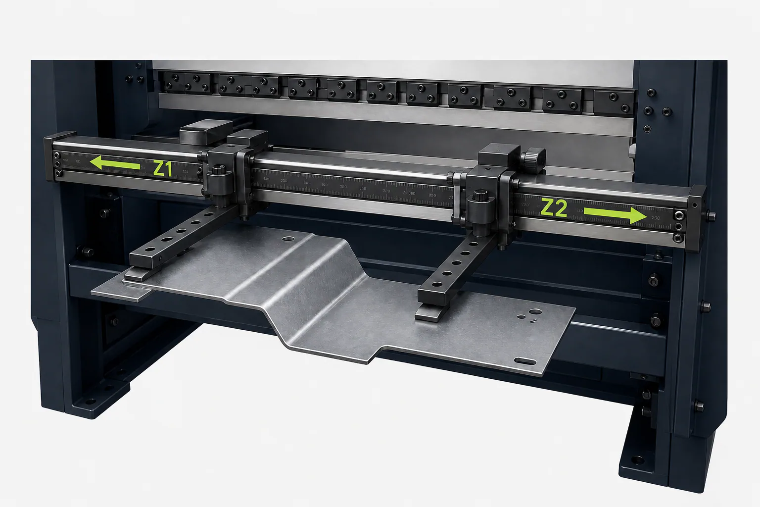
- Z1 / Z2Sideways finger position
Why “4, 6 or 7 axes” is not a complete answer
The basic idea is normally simple: Y forms the bend, and X repeats the needed flange dimension. R and Z1/Z2 become useful when geometry or bend sequence requires the support height and lateral position to change without manual intervention.
Two machines with the same catalogue count can therefore differ. Ask for the installed motions, independent left/right control, actual travel on each axis and the actions that still remain manual — not just the largest number on a specification sheet.
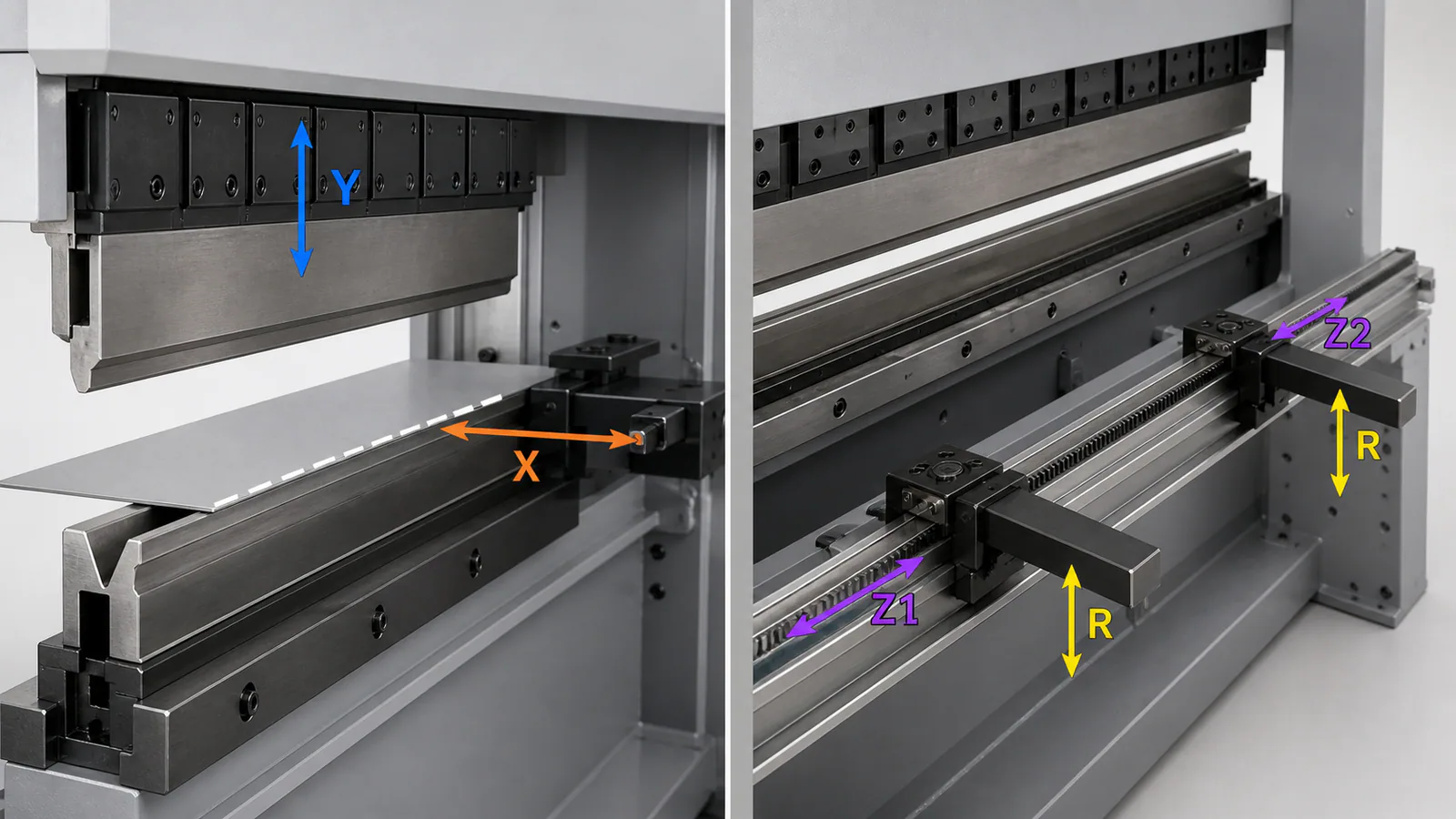
- Basic configurationY + X
- Additional motionsR, Z1, Z2
What a CNC control does — and what it cannot add to the mechanics
CNC means numerical control. The controller stores a part program, guides the bend sequence and commands the installed axes. A simple control accepts dimensions and angles; a more capable one can show the part, tooling and some sequence or collision checks.
Ask what “semi-automatic” means in actions: what positions itself, what the operator resets, when the part is turned, and what is checked after the first piece.
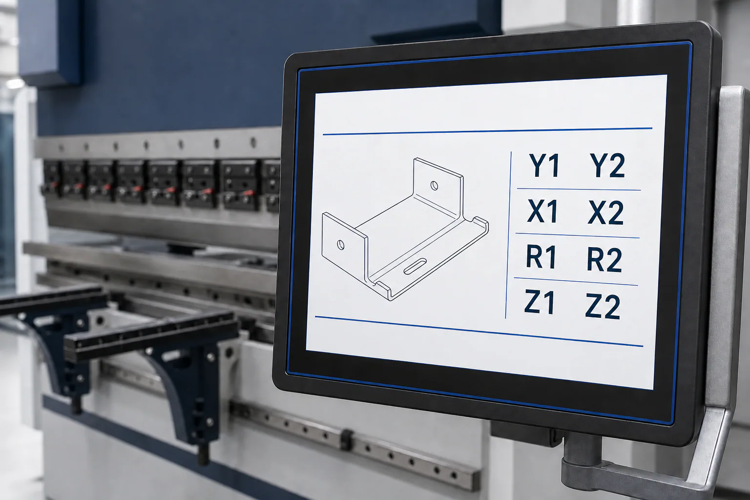
- CNCCoordinates installed axes
How to choose axes without buying unnecessary options
Prepare more than one easy demonstration part: include a simple repeated part, a long part, an asymmetric part, a short-return part and one with several consecutive bends. For each, specify material, thickness, critical flange, tooling and expected batch size.
Ask to see the full route, not one bend: where the sheet references, how X, R and Z change, whether a formed return hits the gauge, which resets stay manual and how the first piece is checked. An added axis earns its place when it removes a specific repeated manual action. Otherwise it does not automatically make the press better.
The article on testing a press brake before purchase helps turn this into an acceptance scenario. Choosing a press brake covers the related capacity, length, tooling and workspace questions.
Select a press brake for your part mix