

One attractive bend does not yet prove that a press brake suits your production
At a demonstration it is easy to show one simple part: flat sheet, familiar tooling, a convenient bend length and an experienced operator. Such a test may confirm that the machine works at all. But it says almost nothing about how it will behave in your day-to-day production flow.
A company does not buy a press brake for one successful angle. What matters is whether typical parts are produced consistently, whether their length and weight are convenient to handle, whether a tooling change turns into half a day of manual work, and whether the result can be repeated after changing to another metal batch. If these points are not checked before purchase, surprises that a marketing demonstration cannot reveal may appear after launch.
The best test is therefore not a competition to make one bend fastest. It is a short but honest rehearsal of your production. You bring your own parts, agree criteria with the supplier, perform several real scenarios and record the outcome. The discussion then moves from “the press looks powerful” to “this is what it does on our jobs”.
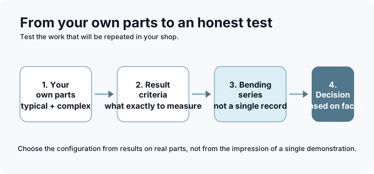
Start with the three jobs that best describe your flow
You do not need dozens of drawings for the first check. Choose three types of work.
The first is a typical production part: one that passes through the shop most often and makes up the main volume. It shows ordinary work—feeding, gauging, bend sequence, cycle time and quality after several repetitions.
The second is a part with the main risk. It may have a long bend, narrow flange, holes near the bend line, a high appearance requirement, difficult gauging or springy material. Do not choose something exotic merely for difficulty. Take what has already caused questions or rejects in your work.
The third is a change to another job: for example, different tooling, thickness, length or operation sequence. This part shows what happens between batches: how long changeover takes, whether settings are retained and whether the operator understands the next step.
If production has different directions—thin sheet, enclosure parts, long panels or stainless-steel parts—add one representative of each. Do not try to squeeze the whole catalogue into one day. A small set whose purpose is clear in advance is far more useful than a large stack of random blanks.

What to prepare before travelling to the test
Along with the parts, prepare the information without which the result will be difficult to compare. For each job, it is advisable to have a drawing or DXF, the material and thickness, the grade or at least a description of the batch, critical dimensions and permitted deviations. If appearance matters, state clearly which side of the part will be visible to the customer and which marks are unacceptable.
Do not forget the real production method. The same geometry can behave differently when the blank has been cut by another process, has a different rolling direction or arrives with protective film. If you have recurring problems — a crack at the bend, an unstable angle, a scratch or difficult positioning — show them before the demonstration begins. The test will then focus on answering the actual question rather than on a general machine presentation.
When two presses are compared, the blanks should be as similar as possible. You cannot draw a conclusion about the difference between machines if one bends metal from one batch and the other uses another. The material itself changes springback, so a fair test begins before the pedal is pressed for the first time.
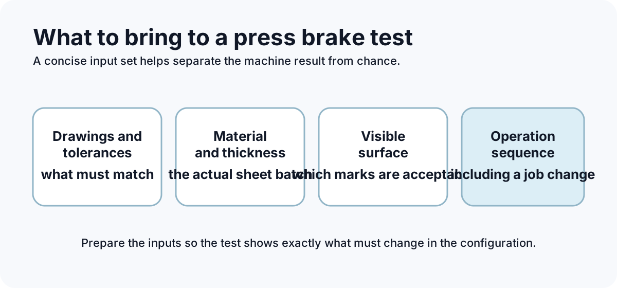
If it is difficult to decide which parts and criteria to bring to the first test, send two or three representative drawings. An L-SEL engineer will help prepare a concise but meaningful verification plan.
Agree the test with an engineerAgree simple criteria before work begins
The phrase “the part must be good quality” sounds reasonable, but each person may understand it differently. It is better to agree several specific points before the test.
- Which dimensions and angles will be checked.
- For which part repeatability matters and where a one-off result is sufficient.
- Which surface marks are acceptable and which are not.
- Whether time measurement is included and from which moment it starts.
- What counts as a changeover: only replacing the program or a full tooling change and setup.
- Which result is a reason to repeat the test or change the configuration.
There is no need to turn this into a complicated contract. One page visible to both sides is enough. It prevents your task from being replaced by a general claim about “high accuracy.”
Observe the first part from blank to measurement
During the first bend, do not rush to judge only the angle. Watch how the operator picks up the blank, whether there is enough support, whether its size is convenient to handle, how the part locates against the backgauges and whether the tooling obstructs access to the required bend. For a large or flexible part, handling often determines comfort and real productivity more strongly than the specified axis speed.
Then examine the result itself. Measure the key angle, flange lengths, the position of holes after bending, diagonals or other dimensions that matter for your design. Inspect the surface in normal light. If the part will be painted or visible in the finished product, small tooling marks can matter more than a tenth of a degree on a non-critical bend.
Ask for several identical parts to be made in sequence. One successful part demonstrates capability; a series demonstrates repeatability. If an angle or dimension begins to drift, the cause must be investigated together: material, tooling, positioning, program, compensation or measurement method.
Tooling and positioning are part of the solution, not an afterthought after choosing the press
A press does not bend metal on its own. The result is affected by the punch, die, their condition, die opening, tooling height, segmentation, clamping method, backgauges and bend sequence. A machine may have sufficient force, yet a particular part may require tooling that blocks access to the next bend or leaves an unwanted mark.
During the test, ask directly which tooling is being used, why it was selected, whether it is included in the proposal, how quickly it can be changed and what happens with a part of another length or with another flange. These are not minor details. This is often where it becomes clear whether you need a universal set, special tooling or a different part design.
If you are already defining the configuration, connect the test result with the guide to selecting a press brake for the production flow. The decision there is treated not as the choice of one parameter, but as a combination of parts, material, format, tooling and work organisation.
If you already understand your main production flow, L-SEL can help turn the test results into a specific configuration: format, force, tooling, backgauges and the required supports.
Select a press configuration
| What to check | What to observe during the test | What to record |
|---|---|---|
| Typical part | Whether ordinary work is produced consistently | Material, tooling, angle, key dimensions and number of repetitions |
| Difficult bend | Whether your main risk has been resolved | The conditions in which the problem appears and what eliminates it |
| Surface | Whether the tooling leaves unacceptable marks | Visible side, protection method and before/after photographs |
| Positioning | Whether feeding and locating the part is convenient for the operator | Required supports, number of people and access to backgauges |
| Changeover | Whether a real transition to another job is possible | Tooling change, program change and verification of the first acceptable part |
| Cycle time | How long the complete operation takes | From feeding the blank to the finished part, without hidden pauses |
Always test the change to another job
Many demonstrations show only the prepared state: tooling is already installed, the program is ready and the operator knows the part. In your workshop, real value often appears between these “ideal” moments. If you work in short runs, changing tooling and completing the first check afterward can occupy a noticeable part of the shift.
After the first part, ask the operator to switch to a second one that genuinely requires another tooling set or arrangement. Watch how the system guides installation, whether segments are confused, whether height must be measured manually, how quickly the operator finds the correct program and how many trial parts are needed before the result becomes stable.
Do not expect every transition to be instantaneous. It is more important to understand the real sequence of work, the number of manual actions and whether there is room to improve them. One answer will be acceptable for series production and another for one-off orders.
Photograph not only the attractive part, but the process itself
A photograph of the finished bend is useful, but it does not explain why the result was achieved. Take several simple photographs: how the tooling is installed, how the part rests against the backgauges, where the operator holds it, and how the visible surface looks before and after bending. This makes it easier to discuss the result calmly after the test, especially if you need to return to the question several days later.

After the test, decide from facts rather than impressions
A good test result can be stated in several sentences: which parts were checked, which parameters were obtained, what the run demonstrated, which tooling is required and which questions remain. If a certain part needs another die, support or sequence, that is not necessarily a disadvantage. What matters is that this is understood before the order and included in the configuration.
A poor conclusion is “we generally liked the press.” It does not answer whether the equipment will cope with your portfolio one month after commissioning. A better conclusion is specific: “typical parts ran consistently; the long profile needs an additional support; the tooling change should be included in the configuration; a protective solution must be checked on decorative stainless steel.”
Such a test does not replace later commissioning, but it substantially reduces the risk of buying a configuration that works well only in someone else's demonstration.
If you already have trial-bending results or a list of representative parts, send them to an L-SEL engineer. The next discussion will then begin with the real task rather than general specifications.
Discuss the test resultIf you compare two presses, keep the conditions identical
A comparison is meaningful only when both machines perform the same task under the same conditions. The drawings, blanks, material, tooling, measurement criteria and operation sequence must all be the same. If one press is shown on a convenient part with selected tooling and the other on another thickness or sequence, the conclusion will say more about how the demonstrations were organised than about the equipment.
Start with a typical scenario. Let both machines produce a run of identical parts. Then check the difficult part that matters specifically to you. Only after that should you move to a tooling or program change. In every scenario, observe the same set of indicators: full operation time, number of manual actions, angle stability, surface quality, ease of feeding and the result of the first acceptable part after changeover.
Do not turn the test into a mathematical ranking made from dozens of incomparable figures. One machine may be slightly faster on a typical bend, while the other handles your long parts better or provides a simpler transition between runs. In that case, identify which factor affects the larger share of your production time.
Measure the part in the order that matters to the customer
After bending, it is easy to spend all the available time checking one angle. For the finished product, however, other factors may be more critical: whether holes align during assembly, whether a long panel is distorted, whether the part fits the adjoining structure and whether tooling leaves a mark on the visible side.
Before the test, divide measurements into three groups. The first is functional: anything without which the part cannot be assembled or cannot work. The second is visual: surface, symmetry and straightness when the end user will see them. The third is diagnostic: measurements that help explain a deviation, such as actual sheet thickness or the positioning reference.
This order makes the discussion practical. Instead of the abstract statement that “the machine is accurate or inaccurate,” you see exactly what affects the finished product. If a critical dimension is stable while a secondary parameter needs correction, that is one situation. If the parts do not fit at assembly, even an excellent angle does not rescue the configuration.
Evaluate the operator's work without shifting everything onto the person
A modern press may have good software, automatic compensation and fast axes. Yet the operator prepares the blank, reads the assignment, installs tooling, checks the first part and responds to unusual situations. If the interface is unclear, the backgauges are difficult to set or a heavy part is awkward to hold, the specified capabilities will not turn into a stable result.
Ask an operator who did not prepare the demonstration in advance to complete one of your scenarios. Check whether program names are clear, the tooling sequence is visible, there are no hidden actions that must be remembered, and there is a safe place for blanks and finished parts. If long workpieces are planned, assess the number of people required or the possibility of using supports and auxiliary systems.
This is not a test of one person's skill. It is a way to see whether the configuration suits your daily pace. A good outcome is when the operator can explain what is being done and why, while the system helps prevent an important step from being missed.
Do not forget the parts that may appear six months from now
A press is purchased for long-term use, so the future direction deserves a brief discussion during the test. Today you may bend mainly thin sheet but already plan longer panels. Or you may currently use one tooling type while a customer is requesting new geometry. There is no need to buy “the maximum just in case,” but the configuration should not be assessed as if your product will never change.
Make a short list of possible changes: another thickness, greater length, new material, a surface requirement, feeding automation or more frequent changeovers. Do not seek an immediate yes-or-no answer for each. It is enough to understand whether the change will require different tooling, another support, a new program, an upgrade or is already beyond the machine's capability.
This approach protects against two extremes: buying a press that becomes a bottleneck tomorrow or overpaying for functions that will never be used. The choice should follow the real direction of your production.
Five questions to take away from the demonstration
Before making the final decision, give yourself clear answers.
1. Did our typical parts pass without unexpected manual workarounds? 2. Do we understand what the difficult part requires: tooling, support, a program change or another sequence? 3. Is the complete cycle time acceptable, including feeding and inspection rather than only press movement? 4. Is it clear what changeover between two real jobs looks like? 5. Which limitations remain, and are they acceptable for our plan for the next several years?
If most questions have specific answers, the test has fulfilled its main role. If the answer is “we will need to look at that later,” define a separate scenario and check it before signing the specification.
If the result is unsatisfactory, identify the cause first
An unsuccessful test does not always mean that the press is “bad.” The angle may differ because of actual thickness or metal properties. A long part may need a different support method. On a decorative surface, the mark may come not from the machine itself but from unsuitable tooling or the absence of protective film. Combining all of this into one score makes the decision arbitrary.
It is useful to divide the problem into three parts. First, does the machine suit the task in terms of force, length and working area? Second, have the tooling, positioning and program been selected correctly? Third, were the material and part prepared in the same way they will be in production? Only then is it clear whether to change the configuration, tooling, process or criterion.
Do not ask the supplier to hide a trial part that failed. It provides the most information. Photograph it, measure the deviation and record the material and tooling. If the result becomes stable after correction, that is also a good outcome: you know which solution works instead of seeing only one successful example.
What to agree before placing the order
After a successful test, another important question arises: will everything used during the demonstration be included in your delivery? Clarify the scope of tooling, supports, measurement systems, software, training, installation and service. If the result was achieved with a special punch or die, that item must not remain only part of a verbal discussion.
Also record which data you will provide before commissioning: drawings, a material list, typical programs, electrical and space requirements, unloading conditions and responsible people. A well-prepared launch does not begin by looking for samples on the day the service engineer arrives. It continues the logic of the test: the machine, tooling and your parts must come together in one real process.
If some future work has not yet been tested, mark it as a separate risk. This is more honest than describing it as guaranteed. If necessary, prepare another set of parts or agree separately on the possibility of an additional test.