

The acceptance test is for the future operation, not just the camera
In a demonstration, a machine vision system often sees one clean part in a convenient position. In production, metal may shine at a different angle, carry traces of oil, scale, or scratches, or be partly covered by a neighboring part. If a robot has to pick the part, what matters is not an attractive image or the mere presence of a point cloud, but a stable result from the complete cell: whether the system finds an acceptable gripping point, whether the robot can reach it without a collision, and whether the cycle stays within the required time.
An acceptance test is therefore a pre-agreed evaluation performed on real or representative production parts. It is needed before purchase or final approval of the solution so that both sides understand the limits of its applicability. This is especially important with shiny metal: the label “3D” by itself does not guarantee equally reliable measurement of every surface.
This article does not replace engineering design and does not establish universal numerical standards. Its purpose is to help define a test that represents the real solution rather than the most convenient demonstration scene.
Why shiny, dark, and contaminated metal changes the result
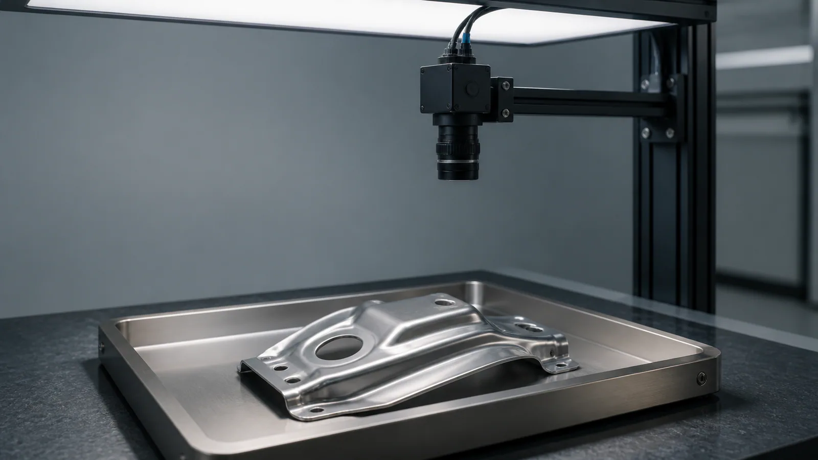
An optical sensor obtains information from light returning from the surface. A matte part often scatters reflected light more broadly. On polished or mirror-like metal, a large share of the light may travel in a direction where the camera cannot see it; in another position, the image may instead contain a bright saturated area. Dark coatings, scale, oil, dust, and local scratches also change the contrast or completeness of the measured data.
This does not mean that shiny metal “cannot be scanned.” Different 2D/3D measurement principles, wavelengths, optics, lighting, and algorithms behave differently. For example, manufacturers offer sensors and modes specifically for specular surfaces, while industrial lighting can use polarization, diffusion, or a different lighting geometry to reduce glare. But the usefulness of a particular combination must be confirmed on your part rather than inferred from someone else's demonstration.
To choose the sensor class itself, first review the logic of 2D and 3D machine vision. The next question addressed here is different: whether the selected system remains stable once the surface and placement are no longer ideal.

Build a sample that contains more than the “best” parts
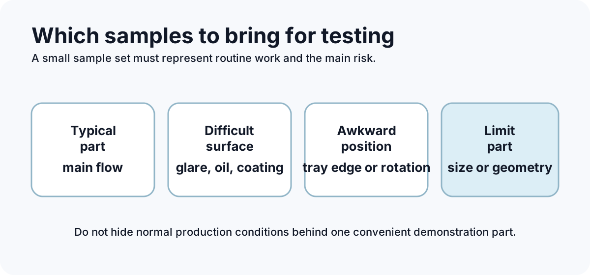
The most common mistake is to test one presentation-ready part. For an acceptance test, it is better to agree on a small but varied sample of what the system will actually see:
- different grades or surface states if they occur in the production flow;
- typical and limiting sizes, thicknesses, holes, edges, and radii;
- parts with normal production oil, dust, or processing marks—without artificial deterioration, but also without cosmetic cleaning;
- several permitted orientations, including those that make viewing or gripping more difficult;
- the real trays, pallets, container, fixture, and background if they are part of the task;
- repeated trials of the same situation to distinguish one lucky image from a repeatable result.
There is no need to artificially create every possible emergency situation. It is more important to state separately which conditions are inside the declared operating range and which conditions the system must detect and correctly reject or send for manual review.
| Test group | What to vary | What to record in the result |
|---|---|---|
| Surface | Matte, ground, shiny, or dark metal; normal coatings | Whether there is enough data for the required decision, not merely whether “an image exists” |
| Part condition | Typical traces of oil, dust, scale, and scratches | Which states are acceptable and which require inspection or rejection |
| Geometry | Size, holes, edges, curvature, and narrow areas | Whether they affect localization, gripper access, or collision risk |
| Position | Angle, height, overlap, and distance to the camera | Repeatability of the decision throughout the required working volume |
| Cycle | Rescans, failed picks, and transfer to the robot | Detection-to-pick time, frequency of repeats, and safe behavior when no decision is available |
Agree on the decision the system must provide before the demonstration
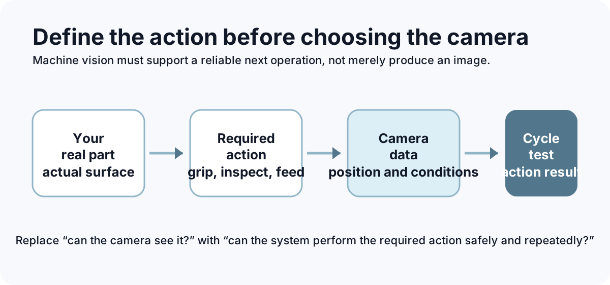
The phrase “the camera must see the part” is too vague. In one cell, coordinates for rough guidance are sufficient because the part is located in a fixture after picking. In another, the system must estimate the spatial pose, assess gripper access, and prevent a collision with the container wall. These tasks have different success criteria.
Before the test, it is useful to agree in writing on:
1. The production action. What happens after recognition: gripping, inspection, sorting, tool guidance, or transfer to an operator. 2. The acceptable result. What position, orientation, or classification is sufficient for that action. 3. The known range of scenes. Which parts, coatings, contamination, heights, and orientations are included in the test. 4. Behavior when no decision is available. Whether the system must rescan, skip the part, signal the operator, or stop safely. 5. The counting method. Which attempts are counted, how repeats are recorded, and what qualifies as successful completion of the cycle.
This description is useful to both the supplier and the customer. It does not promise what is physically impossible, but it prevents a working criterion from being replaced by an attractive demonstration.
Measure the complete cycle, not one successful scan
For a robotic cell, the acceptance test must end with the action for which the vision system is being installed. If the robot cannot pick the part reliably after localization, the system has not passed the actual test regardless of image quality.
A practical sequence to record is: scene acquisition → processing → pose/grip decision → coordinate transfer → robot movement → confirmation of a successful operation. Rescanning, selecting another candidate, a failed pick, and manual intervention should be recorded separately. These events often determine the real throughput of the robotic section, rather than the specified time of one measurement.
If parts lie in a container, the test must cover more than the first convenient picks. Visibility, accessibility, and collisions are additionally important for this task class; they are discussed in detail in the article on robotic picking of randomly arranged parts from a container.

Change one condition at a time so that the cause remains clear
When a test goes badly, it is tempting to change the lighting, camera position, algorithm settings, and feeding method at the same time. After that, it is difficult to understand what actually helped. A more practical approach is to change one condition at a time and record the result briefly.
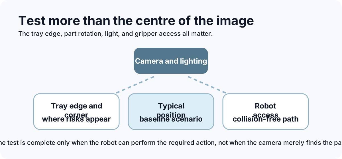
Start with a typical part in the basic position. Then change only the angle. Return the angle and add a normal trace of oil. Next, test a position near the tray wall. This produces a map of the real limits instead of a vague “works or does not work” assessment: where the system is stable, where it needs different lighting, and where the process itself should be changed mechanically.
Sometimes the best solution is not a more complicated algorithm but more predictable feeding: add location features, separate the parts, change the background, remove stray light, or fix the distance to the camera. Machine vision works as part of a system, not in isolation.
How to make a decision after the test
The system does not have to produce an ideal result in every artificial situation. The important questions are whether it covers the normal production range, what its known boundary is, and how it behaves at that boundary.
A useful conclusion is specific: “With these parts, this lighting, and this tray, the robot picks reliably; the dark oily part needs another mode; when a part is fully covered, the system does not guess but sends it for another check.” Such a result can be used both in the technical specification and in final acceptance.
If the camera regularly loses the part in a normal production condition, do not hide it. Before purchase, change the optics, lighting, feeding method, gripper, or task definition. That is cheaper than explaining repeated robot stops after launch.
Test the working volume and calibration stability
A system may work well in the center of the field of view and worse near the boundary of the working volume, at another angle, or after a mounting change. If the task uses a relationship between the camera and the robot, the acceptance test must verify the result at representative positions rather than in only one convenient location.
It is also important to define which change requires a control check: moving the camera or light, replacing a protective window, an impact on the bracket, service work, or a change of tool or fixture. Final accuracy depends on the entire camera–robot chain, the mechanics, the gripper, and the part location—not only on a sensor specification.
Do not demand “one accuracy everywhere” until the working volume, part, and final operation have been defined. Instead, the test should show whether actual repeatability is sufficient for the stated action.
Evaluate lighting and camera mounting together
The camera, lens, light, and bracket form one unit. Changing only the camera or only the lamp is often not enough. Mounting height determines the field of view and the size of the part in the image. The viewing angle affects glare and whether the camera obstructs the robot. Lighting can emphasize an edge while also creating a bright spot on a polished area.
During the test, inspect the physical installation as well as the screen. Is there room for cables and service? Can the robot strike the light at an extreme position? Can daylight from a window, an open door, or a neighboring station enter the image? Can the camera be returned to the same position after changing a part or fixture?
There is no need to demand one universal setup for every possible surface. Record the lighting used, the part range for which it is adjusted, and what must be rechecked after the material changes.
A useful test reveals the operating boundary instead of hiding failures
An unsuccessful measurement does not always mean that the solution is unsuitable. It may show that a particular surface needs different lighting, another angle, additional mechanical location, a changed feeding method, or another sensor technology. But the event must be recorded as a test result rather than disappearing from the summary.
It is useful to separate three things in the final protocol:
- what the system performs reliably within the agreed range;
- which conditions require a separate mode, a repeated check, or a process change;
- which states are outside the current scope of the solution and how the cell behaves safely.
This approach reduces the risk of buying a system based on a demonstration that does not reproduce the real flow. It also gives the engineer clear input for improving the cell instead of a general message that “the camera sometimes cannot see the metal.”
A short brief to prepare for the test
Before sending the parts, one document is enough: a description of the operation, photos or video of the real feed, a list of surfaces and coatings, part dimensions and mass, permitted orientations, required cycle time, a description of the gripper, safe-failure requirements, and several samples in “difficult” states. If the test concerns a complete robotic cell, add the constraints of its working volume and the next operation.
This does not replace engineering design, but it makes the first technical discussion specific: the test evaluates the real system rather than an abstract camera.
Include a person who knows the real process
The supplier's engineer knows the equipment, but may not know where your part tends to jam, why the operator sometimes wipes its surface, how the tray changes by the end of the shift, or which mistake is most expensive for the next operation. Invite a technologist, operator, or supervisor who knows the process from daily work.
This person helps define realistic scenarios: which side of the part normally arrives first, what contamination is normal, where the part must go, how often the product changes, and what happens after a failed pick. After the test, ask each participant to name one result that has been demonstrated and one condition that still needs checking. Strongly different answers mean that the acceptance criteria are still too vague.
Do not rely on universal promises
Do not ask the supplier to promise that the system will “see everything.” Real production always has limits: a part may be fully hidden, its surface may differ radically from the tested sample, or the tray may contain no safe gripping point. A strong solution is not one advertised as limitless, but one whose boundaries are known and whose behavior is predictable.
Replace broad promises with statements that can be tested: “the system works reliably with these surfaces,” “at this degree of overlap it selects another part,” “outside the working volume it alerts the operator,” and “after a lighting change a control check is performed.” These conditions can be recorded in the protocol and handed to the launch team.
This approach does not reduce the value of machine vision. It turns it into a useful engineering tool instead of a source of undefined expectations.