

Suitable applications
Production of conductive busbars for switchboards, distribution assemblies and electrical equipment: holes, blank cutting, horizontal bends and vertical bends.
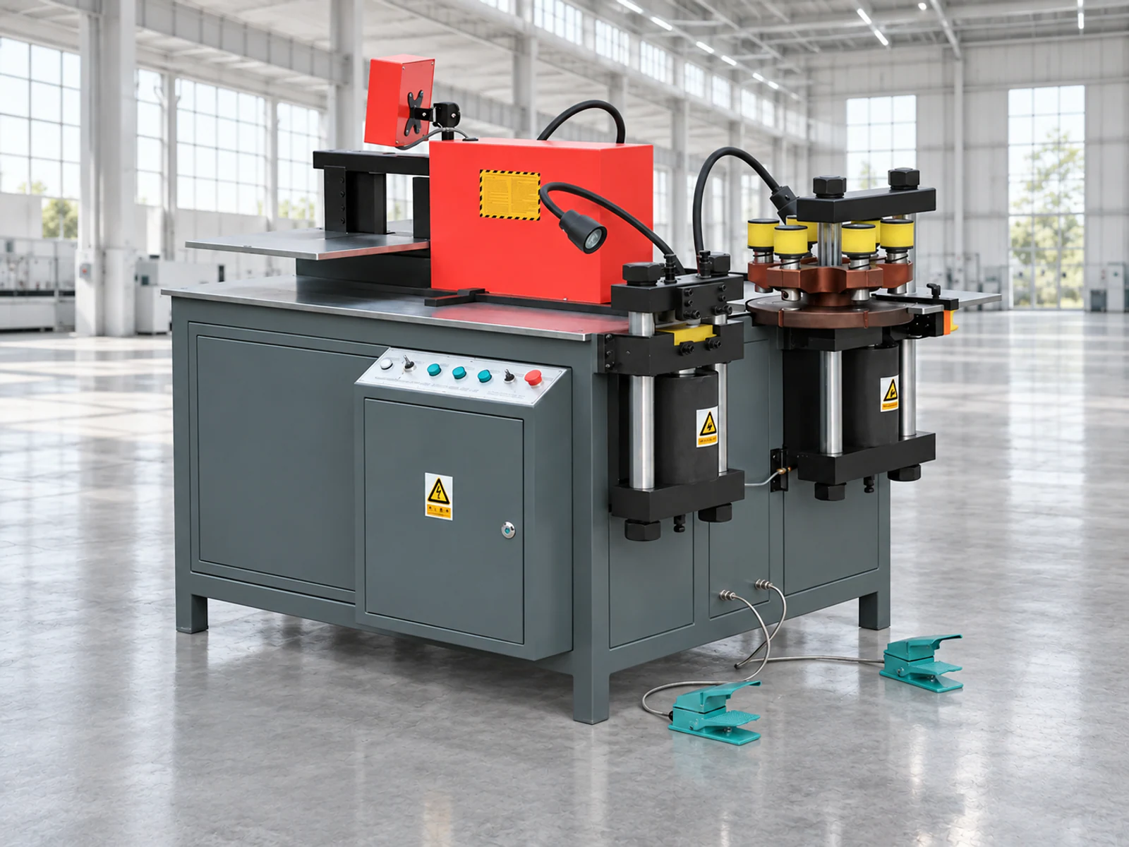
The image is for reference. Actual appearance and configuration may vary.
Article: 10011
Three work units for punching, shearing and bending copper or aluminium busbars in one machine.
Punching, shearing and bending units share one hydraulic machine with two work tables. The source describes the units as independent; the permitted simultaneous workflow is confirmed for the actual configuration.
Punching holes in a copper busbar
Production of conductive busbars for switchboards, distribution assemblies and electrical equipment: holes, blank cutting, horizontal bends and vertical bends.
JPSK-303ESK combines three sequential operations at one workstation. Compare it with separate punching, shearing and bending machines through the busbar range, changeover time and required dies. The 160 × 12 mm limit does not mean every geometry is available across that entire envelope at once.
| Model | Force, kN | Dimensions L × W × H, mm | Machine weight, t |
|---|---|---|---|
| JPSK-303ESK | 300 | 1780 × 1400 × 1300 | 1.4 |
| Dimensions L × W × H, mm | 1780 × 1400 × 1300 |
|---|---|
| Machine weight, t | 1.4 |
For selection, send the busbar material, width and thickness, hole and bend drawing, minimum edge distances and required volume. We will check the operations, dies and process sequence.
Hole and bend geometry depends on the installed tooling. Special dies for oval or shaped holes, vertical and U-bending, twisting, embossing and cable-lug pressing are agreed separately.
The values describe the version in the supplied source material. Material, geometry, minimum edge distances and the matching die are checked before ordering.
| Parameter | Value |
|---|---|
| Punching force | 300 kN |
| Round-hole diameter | Ø4.3–Ø25 mm |
| Maximum busbar for punching | 160 × 12 mm |
| Maximum busbar for shearing | 160 × 12 mm |
| Horizontal bending force | 300 kN |
| Maximum busbar for horizontal bending | 160 × 12 mm |
| Maximum vertical-bending width | 100 mm |
| Maximum vertical-bending angle | 90° |
| Bend-angle accuracy | ±1° |
| Bend-angle repeatability | ±0.5° |
| Dimensions L × W × H | 1780 × 1400 × 1300 mm |
| Drives | 3 × 4 kW |
| Weight | 1400 kg |
The source configuration lists a Siemens PLC, Schneider contactors and thermal relays, a Yuken directional valve and a separate hydraulic station. Exact component series are recorded in the final specification.
The source marks a loading table as a recommended option. Separate dies cover embossing, low-mark bending, twisting and cable-lug pressing. Compatibility and working limits are agreed for each die.
Send a drawing or photograph of the part, material, thickness, blank size and required output. This lets us compare configurations against your job, not just their power rating.
Tell us what you would like to clarify. Add drawings, photos or the required configuration reference to your request if available.
Discuss configuration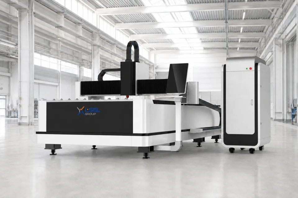
LF3015CN
Article: 10001
A single open 3000 × 1500 mm table with direct sheet access. A model for straightforward stock logistics and a configuration matched to the actual job.
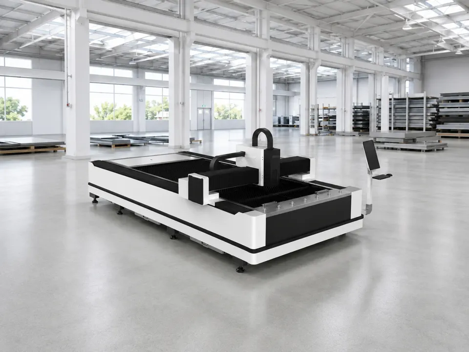
LF3015LN, LF4020LN, LF6025LN
Article: 10004
An open-access working area in several standard formats. A sheet cutting series configured for your application.
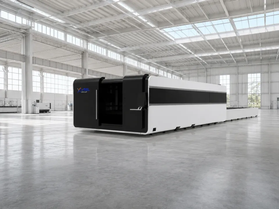
LF3015GA, LF4020GA, LF6025GA
Article: 10003
A protective enclosure and exchange tables for organised sheet processing. While the machine cuts on one table, the other can be prepared for the next cycle.